
Member having internal cooling passage

a technology of internal cooling and member, which is applied in the direction of machines/engines, mechanical equipment, liquid fuel engines, etc., can solve the problems of deterioration of the heat transfer performance of the whole member, and achieve the effect of reducing a recirculation zone and high heat transfer performan

Active Publication Date: 2006-10-26
MITSUBISHI POWER LTD
View PDF4 Cites 29 Cited by
  • Summary
  • Abstract
  • Description
  • Claims
  • Application Information

AI Technical Summary

Benefits of technology

[0009] It is desirable to provide a member having high heat transfer performance by reducing a recirculation zone at a downstream side of a rib.
[0011] According to the present invention, it is possible to provide a member having high heat transfer performance by reducing a recirculation zone at a downstream side of a rib.

Problems solved by technology

Thus, heat transfer performance of the whole member may deteriorate.

Method used


Image

  • Member having internal cooling passage
  • Member having internal cooling passage
  • Member having internal cooling passage

Examples


Embodiment Construction

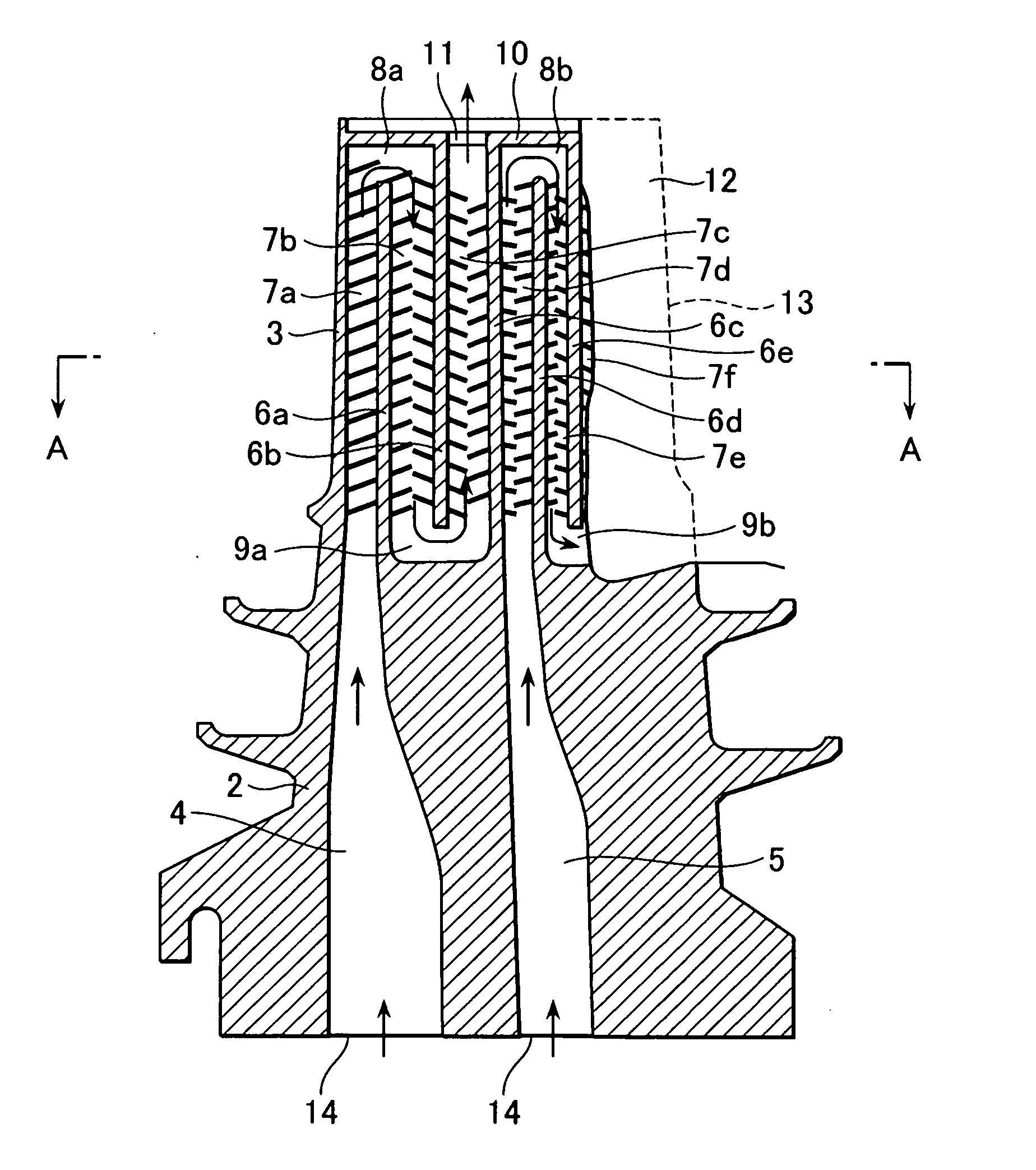
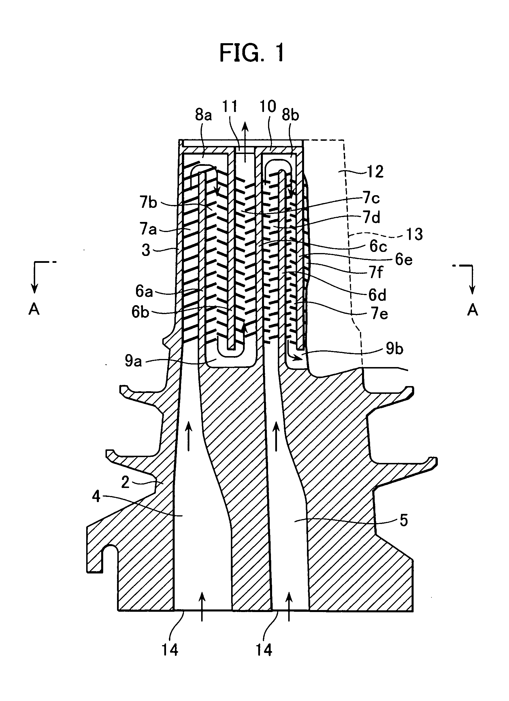
[0024] There are provided various members which each have an internal cooling passage formed therein and having opposed wall surfaces between which a medium flows to cool a parent material. However, here, for example, a most representative gas turbine blade will be described.

[0025] A general gas turbine is configured to obtain high temperature and high pressure gas generated by the combustion of fuel with high pressure air compressed by a compressor to drive a turbine. Rotation energy of the driven turbine is generally converted to air energy by a generator coupled to the turbine.

[0026] Here, since a part of a high temperature section of the gas turbine, and more particularly, a heat load of a blade becomes higher, the blade has an internal cooling passage. Concretely saying, a cavity is provided in the blade to be used as the cooling passage and gas discharged or extracted from the compressor is fed into the cooling passage to cool the blade to an allowable temperature or less.

[...


PUM


Abstract

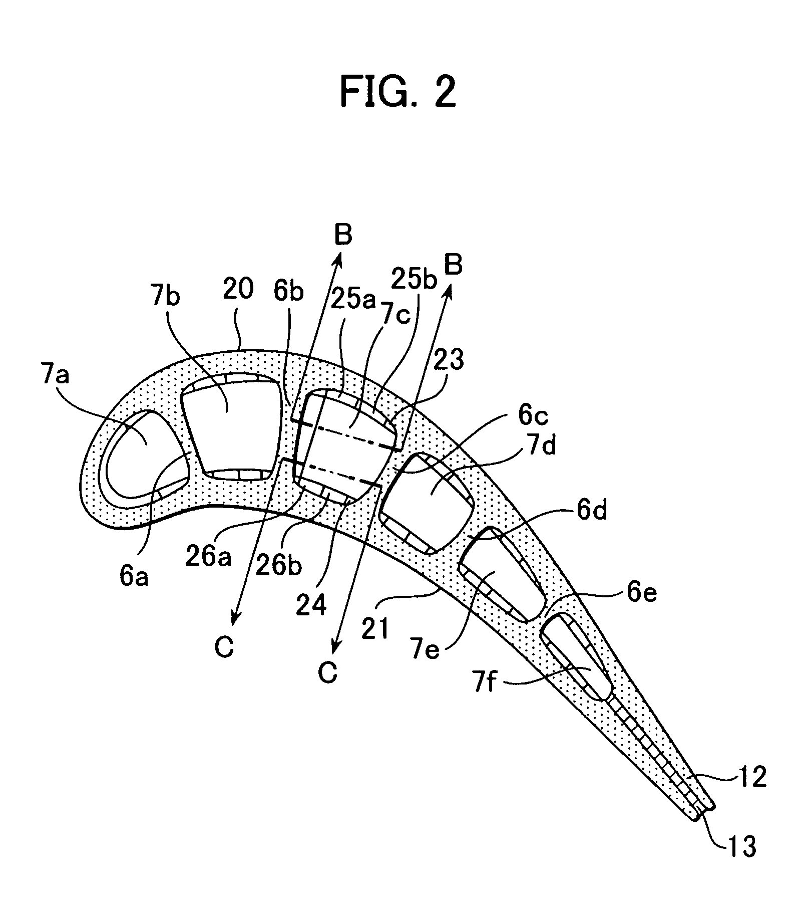
Provided is a member having an internal cooling passage 7c formed therein and having opposed partition walls 6b, 6c between which a medium flows to cool a parent material, including a first heat transfer rib 25a which extends from almost the center between the opposed partition walls 6b, 6c to one partition wall 6c and slants in a downstream direction of the medium, and a second heat transfer rib 25b which extends from almost the center between the opposed partition walls 6b, 6c to the other partition wall 6b and slants in the downstream direction of the medium, wherein a slit 70a or 70b which passes through between an upstream side of the cooling passage 7c and a downstream side thereof is formed in the first heat transfer rib 70a or the second heat transfer rib 70b.

Description

BACKGROUND OF THE INVENTION [0001] 1. Field of the Invention [0002] The present invention relates to improvement of a member having an internal cooling passage, and more particularly, to improvement of a member having an internal cooling passage with a wall surface which possesses cooling ribs. [0003] 2. Description of Related Art [0004] In the related art, for improvement of heat transfer efficiency in an internal cooling passage of a member, a method of causing turbulence flow in air flow of a heat transfer surface or destroying a boundary layer is known. In addition, there is a method of providing a plurality of protrusions on a blade. [0005] For example, in JP-A-05-10101 (U.S. Pat. No. 5,395,212; FIG. 3), a plurality of ribs is provided in the internal cooling passage of a member and arranged in a staggered manner with respect to flow of a medium in the cooling passage such that turbulent flow is caused in the medium on a heat transfer surface to obtain a large cooling heat tran...

Claims


Application Information

Patent Timeline
Patent Type & Authority Applications(United States)
IPC IPC(8): F01D5/18
CPCF05D2260/22141F01D5/187F01D5/20
Inventor KIZUKA, NOBUAKIHORIUCHI, YASUHIROMARUSHIMA, SHINYAKUROKI, HIDETOSHI
Owner MITSUBISHI POWER LTD
Learn More