Torch for electric arc welding or plasma cutting system
a technology of plasma cutting system and torch, which is applied in the direction of plasma welding apparatus, electrode supporting devices, manufacturing tools, etc., can solve the problems of welding and/or cutting system components deteriorating, work will need to be repeated, damage to workpieces,
- Summary
- Abstract
- Description
- Claims
- Application Information
AI Technical Summary
Benefits of technology
Problems solved by technology
Method used
Image

Examples
third embodiment
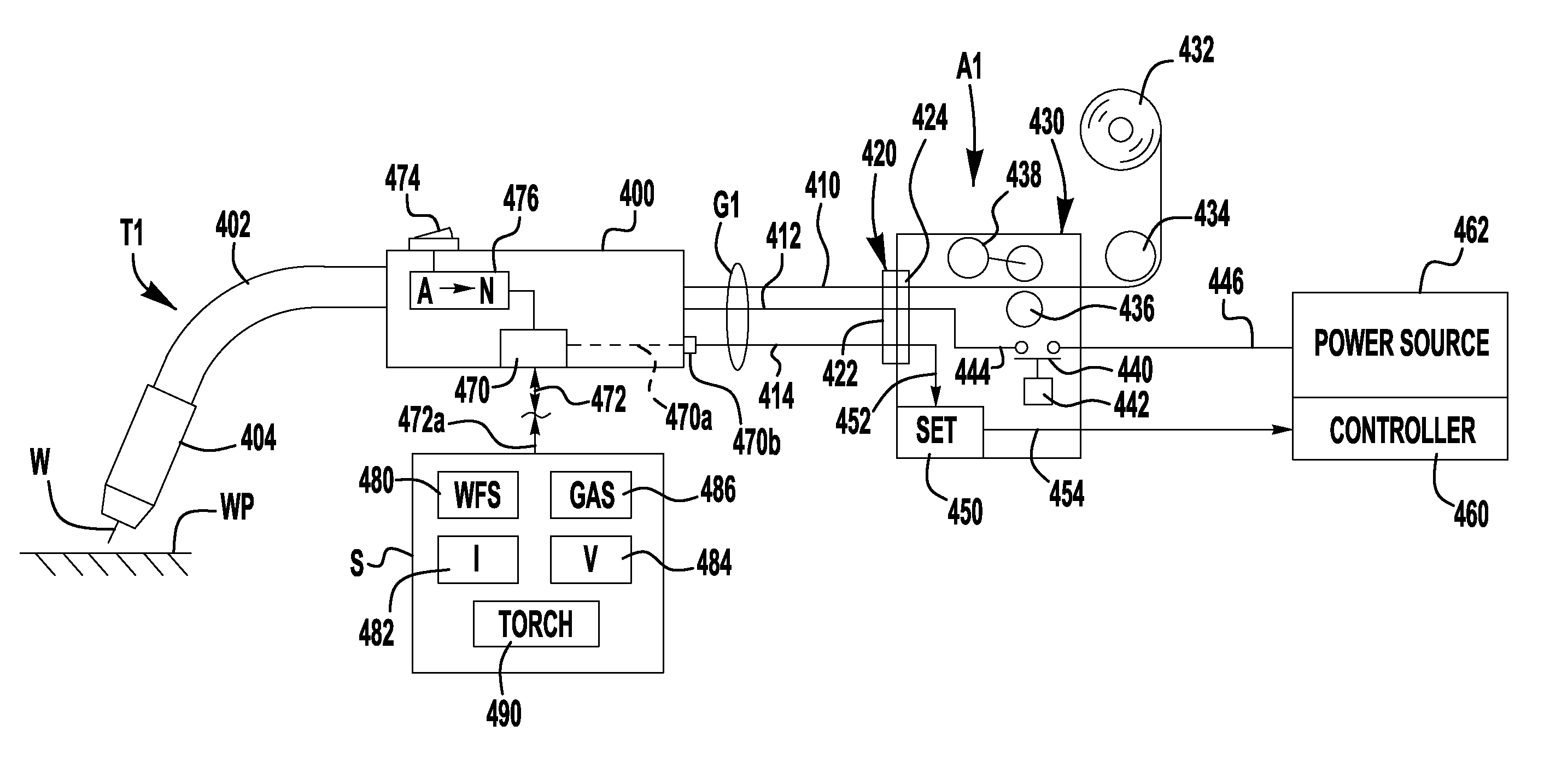
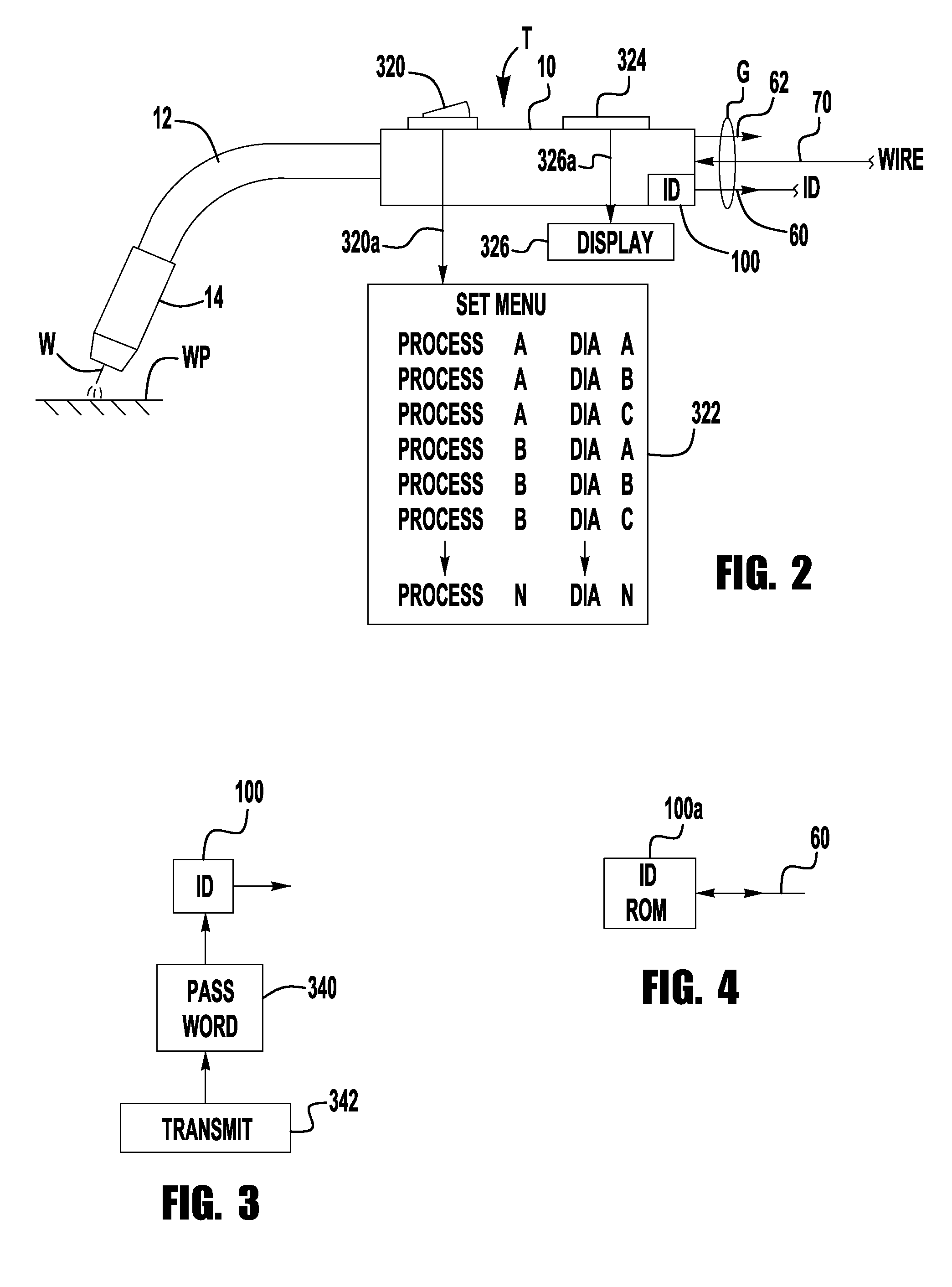
[0027]the invention involves a torch for connection to an electric welding system, as defined above. The torch has a register with a unique identification code, in digital format so that the torch is connected by communication channel to an interface module activated by a given code and / or codes. One code that activates the interface is the unique code of a particular torch connected to the welding system. The interface has an output that sets the weld process parameters. The output channel of the interface transmits digital data to the controller that has a set up circuit for storing the transmitted digital data as control parameters for the power source. Thus, by merely connecting a particular torch to the welding system, the torch is identified and is allowed to activate an interface module. This module sets the parameters in the controller used by the welding system. The identification code for the torch is in memory or register on the torch and is directed through a unique conn...
fifth embodiment
[0029]the invention is a torch with a unique identification code stored in the torch itself. This code is used with a controller including a closed loop circuit to control the weld parameters, such as current and / or voltage and a network to create a special weld procedure. The torch, with the unique identification code stored on the torch, creates an output signal which is decoded for identification by the welding system. Receipt of the proper code creates a network enabling signal. This can be accomplished by connecting the lead carrying the unique identification code from the torch to the welding system. By attaching the novel torch, the network enabling signal is created by a decoded identification of the proper torch. This signal activates the network and converts the controller to the special weld procedure. In this manner, a particular torch designed for a given special operation of the controller is the only type of torch which can activate the special alternative weld proced...
first embodiment
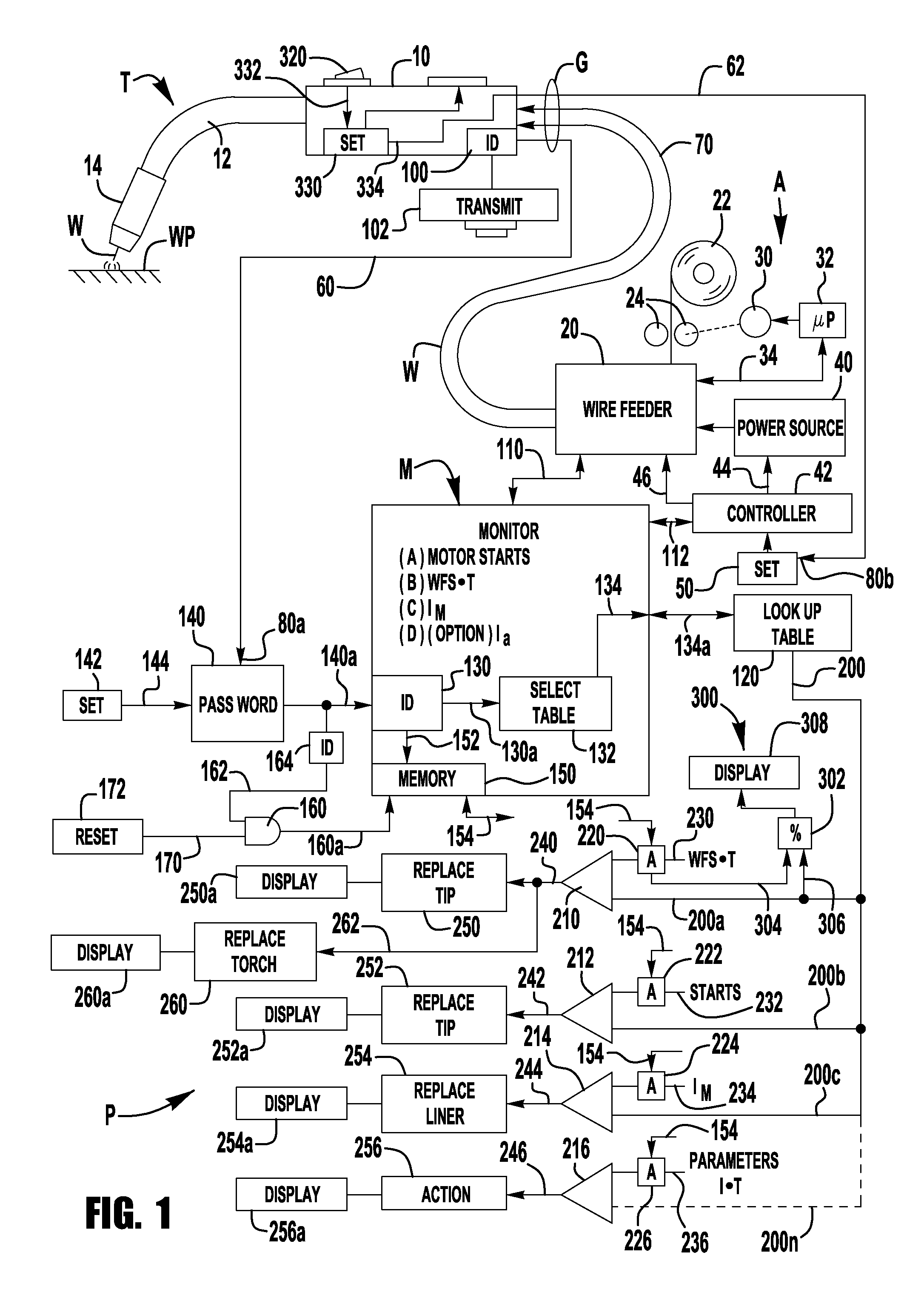
[0036]In accordance with an aspect of the invention, monitor M also provides life meter 300 determining the remaining anticipated life of the torch T before it should be replaced. Life meter 300 includes register 302 that decreases from 100% to 0% by sensing the output of one of the accumulators. As illustrated, the accumulator 220 is read by line 304, together with the limit value for the product of wire feed speed and time. This value appears on line 306. The output of register 302 indicates the amount of life remaining for the particular torch T. This life percentage is displayed by device 308 or is recorded on torch T or with respect to torch T for future use in inventory management. Program P can take other forms; however, the computer program, as described, is the preferred implementation of the invention.
[0037]In accordance with another aspect of torch T, it has a separate and distinct function wherein the torch is connected to the welding system A to provide parameters on de...
PUM
| Property | Measurement | Unit |
|---|---|---|
| Temperature | aaaaa | aaaaa |
| Force | aaaaa | aaaaa |
| Electric potential / voltage | aaaaa | aaaaa |
Abstract
Description
Claims
Application Information
 - R&D Engineer
- R&D Manager
- IP Professional
- Industry Leading Data Capabilities
- Powerful AI technology
- Patent DNA Extraction
Browse by: Latest US Patents, China's latest patents, Technical Efficacy Thesaurus, Application Domain, Technology Topic.
© 2024 PatSnap. All rights reserved.Legal|Privacy policy|Modern Slavery Act Transparency Statement|Sitemap