
Transmission mechanism for dual-shaft hinge

a dual-shaft, hinge technology, applied in the direction of wing accessories, portable computer details, instruments, etc., can solve the problems of high manufacturing and assembly costs, slow and not smooth flip operation, and inconvenient display

Active Publication Date: 2015-06-11
LIANHONG TECH
View PDF9 Cites 37 Cited by
  • Summary
  • Abstract
  • Description
  • Claims
  • Application Information

AI Technical Summary

Benefits of technology

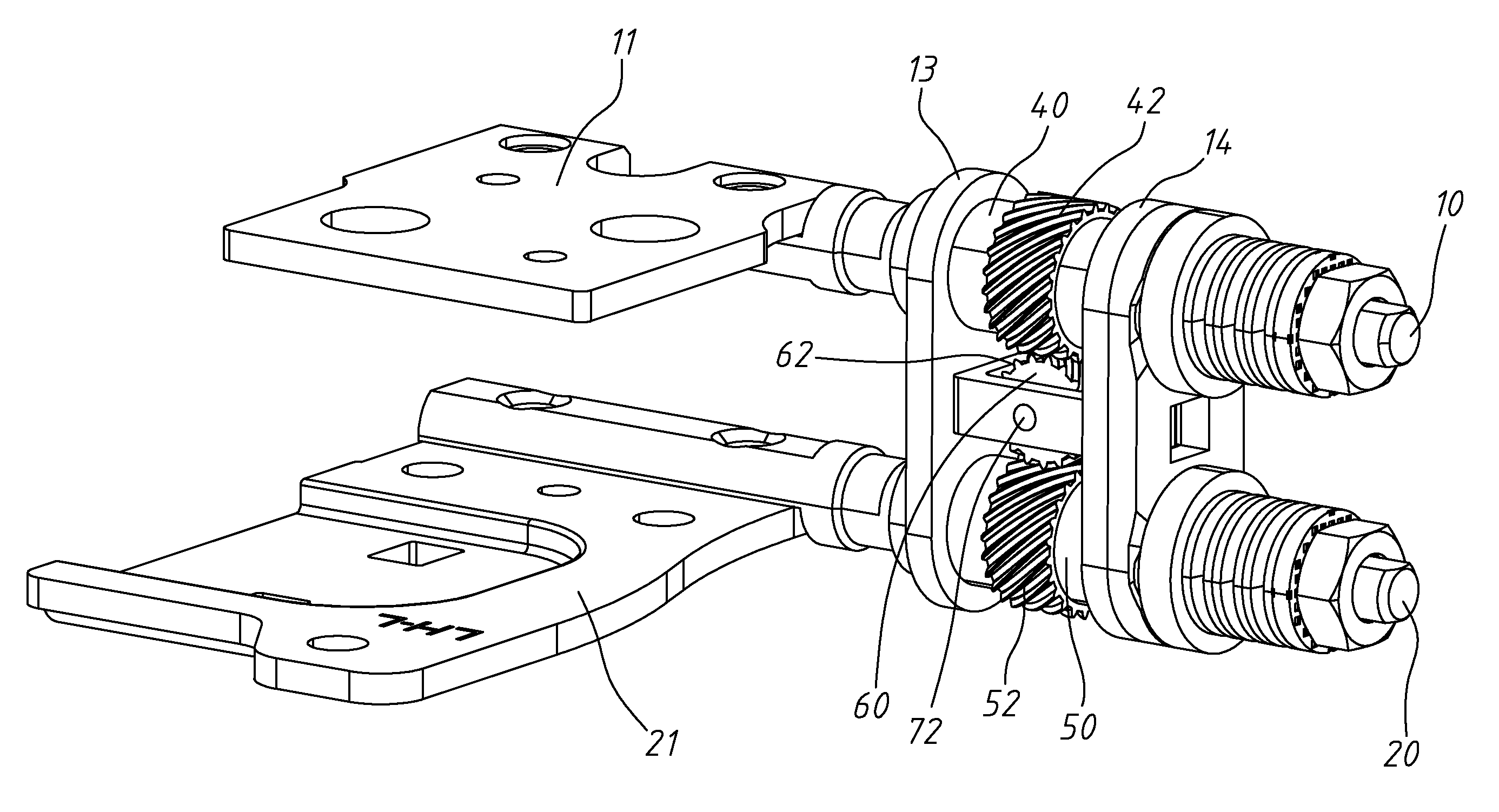
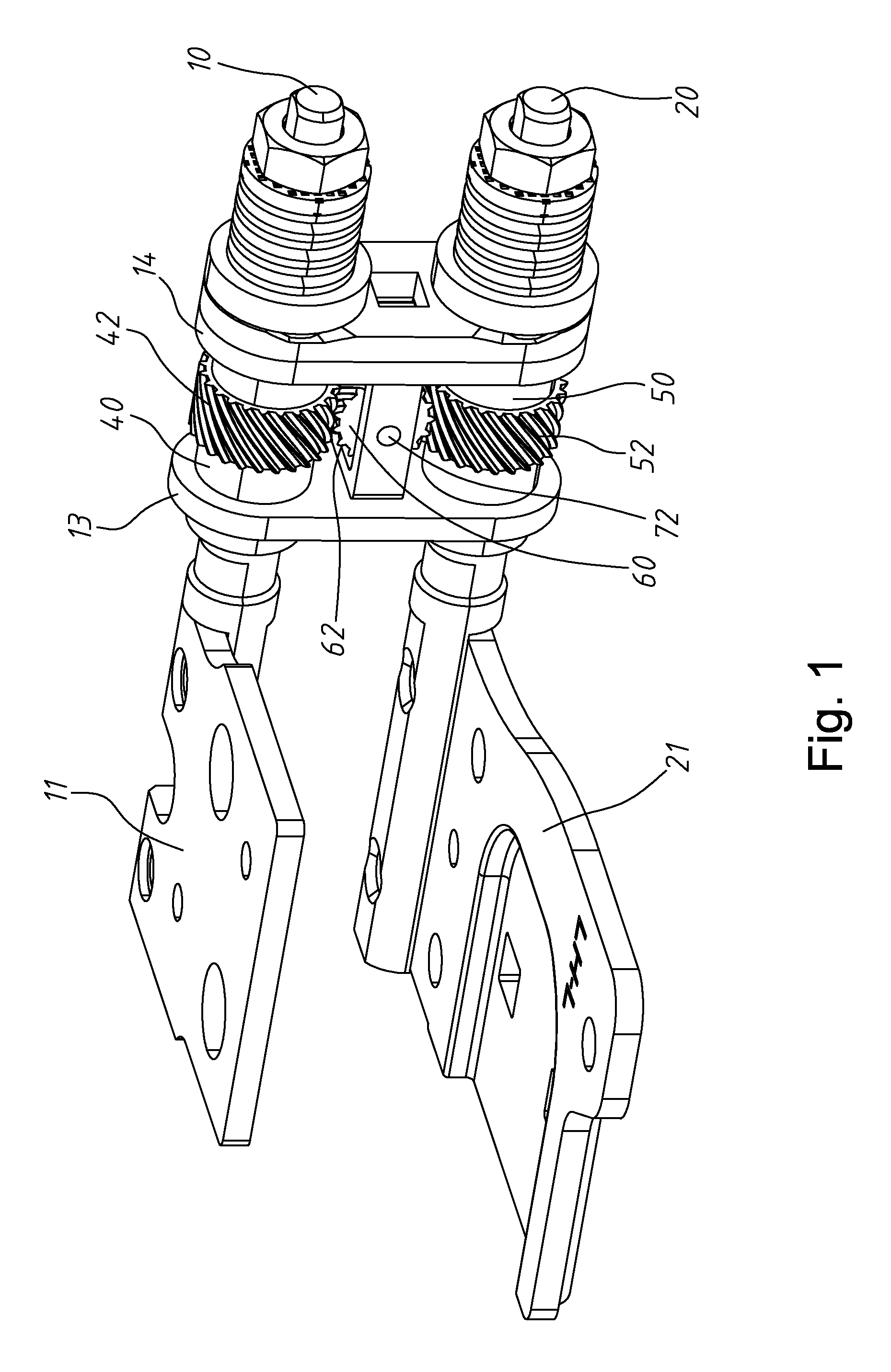
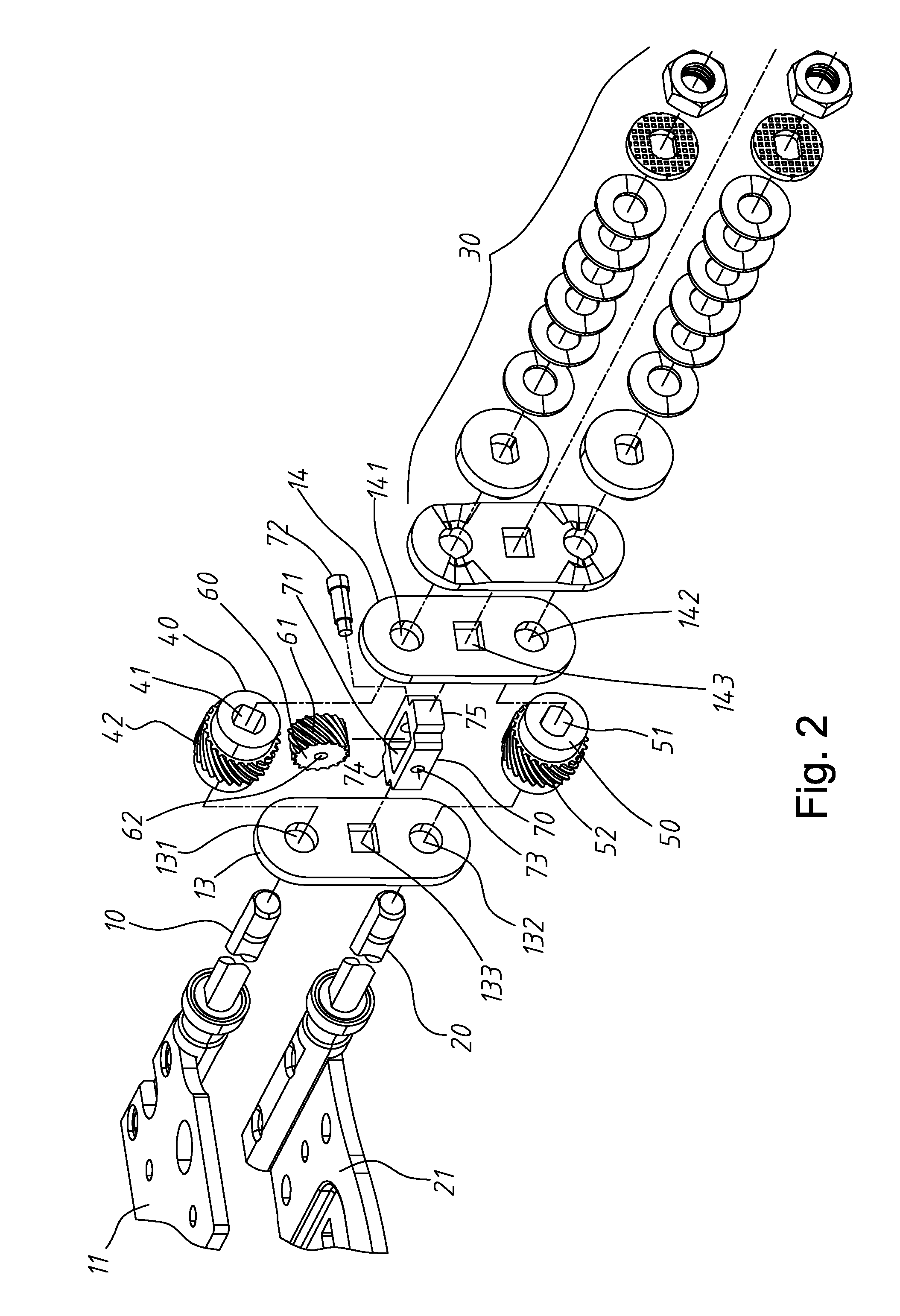
The invention provides a transmission mechanism for a dual shaft hinge. The mechanism includes a first shaft, a second shaft, a first positioning plate, a second positioning plate, a first gear, a second gear, and a middle gear. The first shaft is connected to the first mounting plate and the second shaft is connected to the second mounting plate. The first gear is mounted on the first shaft and has a first helical tooth portion. The second gear is mounted on the second shaft and has a second helical tooth portion with the same tooth profile and helix angle as the first helical tooth portion. The middle gear is disposed between the first gear and the second gear and has a transmitting helical tooth portion skewly engaging the first helical tooth portion and the second helical tooth portion. The positioning plate has a first hole for the first shaft and a second hole for the second shaft. The mechanism allows for smooth and synchronized movement between the two shafts.

Problems solved by technology

The entire rotation mechanism is so complicated that it causes high cost in manufacture and assembly, and also causes slow and not smooth in flip operation.
It is inconvenient for the display flipped 360° by rotated to a predetermined angle by one shaft and then rotated by the other shaft.
The conventional dual-shaft hinge is often equipped with complicated transmission mechanism which occupies large space and is not conducive to miniaturization of the laptop.

Method used


Image

  • Transmission mechanism for dual-shaft hinge
  • Transmission mechanism for dual-shaft hinge
  • Transmission mechanism for dual-shaft hinge

Examples


Embodiment Construction

[0026]The following description is of the best-contemplated mode of carrying out the invention. This description is made for the purpose of illustrating the general principles of the invention and should not be taken in a limiting sense. The scope of the invention is best determined by reference to the appended claims.

[0027]Referring to FIGS. 1-3, a transmission mechanism includes a first shaft 10 and a second shaft 20. One end of the first shaft 10 is joined to a first mounting plate 11 mounted to a display of a laptop, and the other end of the first shaft 10 is joined to a concave washer, a convex washer, an elastic mechanism or a securing mechanism. One end of the second shaft 20 is joined to a second mounting plate 21 mounted to a base of a laptop, and the other end of the second shaft 20 is joined to a concave washer, a convex washer, an elastic mechanism or a securing mechanism.

[0028]The first shaft 10 and the second shaft 20 are parallel and extend through a first positioning...


PUM


Abstract

A transmission mechanism includes a first shaft connected to a first mounting plate; a second shaft connected to a second mounting plate; a first positioning plate through which the first shaft and the second shaft extend rotatably; a second positioning plate, through which the first shaft and the second shaft extend rotatably, spaced from the first positioning plate by a distance; a first gear mounted on the first shaft, disposed between the first positioning plate and the second positioning plate and having a first helical tooth portion; a second gear mounted on the second shaft, disposed between the first positioning plate and the second positioning plate and having a second helical tooth portion having the same tooth profile and helix angle with the first helical tooth portion ; and a middle gear disposed between the first gear and the second gear and having a transmitting helical tooth portion engaging the first helical tooth portion and the second helical tooth portion, wherein the middle gear rotates about an axis skewed with the first shaft and the second shaft.

Description

BACKGROUND OF THE INVENTION[0001]1. Field of the Invention[0002]The invention relates to a transmission mechanism for a dual-shaft hinge, and more particularly to a transmission mechanism using helical gear set to synchronize rotation of two shafts of the hinge.[0003]2. Description of the Related Art[0004]It is a popular design for a display of a laptop detachable from its base. The detached display can be used as a tablet. When the display is joined to the base, is can be rotated to an arbitrary angle with respect to the base by a dual-shaft hinge. By the dual-shaft hinge, the display can even be flipped (rotated 360°) to overlap the base to serve as a tablet.[0005]A conventional dual-shaft hinge includes a first shaft rotated along with the display and a second shaft rotated along with the mainframe. However, when the dual-display is rotated to a large angle or flip to overlap the mainframe by the dual shaft hinge, the display is rotated by one shaft to a specific angle first, and...

Claims


Application Information

Patent Timeline
Patent Type & Authority Applications(United States)
IPC IPC(8): E05D3/12G06F1/16
CPCG06F1/1618E05D3/122G06F1/1681
Inventor CHEN, CHIA-HUILIN, TZU-YUCHEN, YEN-TINGKAO, MIN-HSIANG
Owner LIANHONG TECH
Learn More