Image forming apparatus

Active Publication Date: 2015-06-11
KONICA MINOLTA INC
View PDF5 Cites 1 Cited by
  • Summary
  • Abstract
  • Description
  • Claims
  • Application Information

AI Technical Summary

Benefits of technology

The invention aims to speed up the process of fixing images on paper by determining the optimum temperature for each page and reducing the time it takes to reach the target temperature for the next page, regardless of its location in the system. This will improve overall productivity and efficiency.

Problems solved by technology

However, such a setting is not favorable in terms of power saving, because an unnecessarily large amount of power will be consumed for fixing toner images on a page that does not require such a large amount of heat.
Consequently, this technology reduces the increment of the temperature during the sheet interval period even when the difference between the target fixing temperatures for pages is large, and reduces the waiting time that occurs when raising the fixing temperature, without extending the sheet interval period.
However, if there is no such a page (e.g. when the given page is the first page), it is impossible to reduce the increment of the temperature during the sheet interval period, or to reduce the waiting time.

Method used


Image

  • Image forming apparatus
  • Image forming apparatus
  • Image forming apparatus

Examples


embodiment

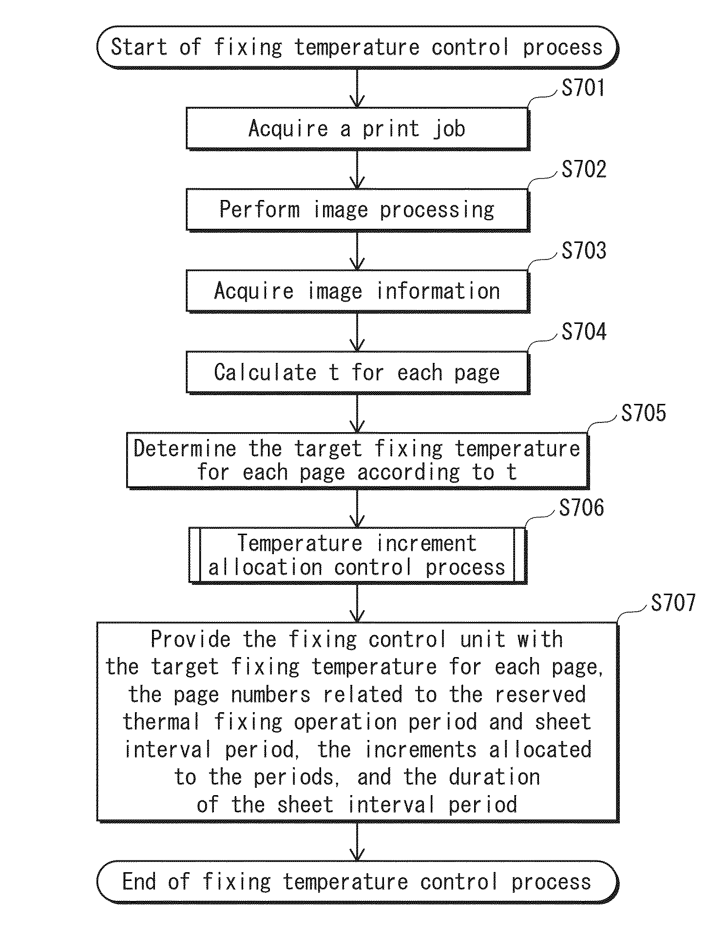
[0034]The following explains an image forming apparatus according to one aspect of the present invention, using an example of a tandem color digital printer (hereinafter, referred to simply as “printer”).

[1] Configuration of Printer

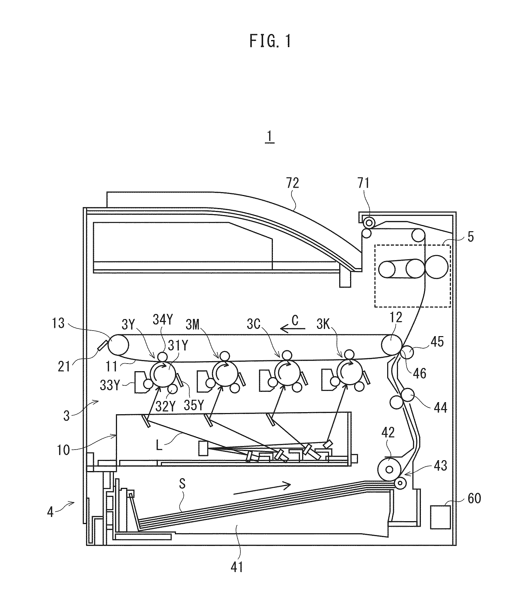
[0035]First, a configuration of a printer 1 pertaining to the present embodiment is described. FIG. 1 shows a configuration of the printer 1 pertaining to the present embodiment. As shown in the drawing, the printer 1 includes an image processing unit 3, a paper feeder 4, a fixing device 5 and a controller 60.

[0036]The printer 1 is connected to a network such as a local area network (LAN). When the printer 1 receives a print command from an externally located terminal (not illustrated) or from an operation panel having a display unit (not illustrated), the printer 1 performs a printing process on a recording sheet by forming respective toner images of yellow, magenta, cyan, and black colors based on the print command, and forming a full-color image by sup...

modified examples

[0119]The present invention is explained based on the above embodiment, but the present invention is of course not limited to the embodiment. For example, the present invention may alternatively be implemented as explained in any of the following modified examples.

[0120](1) In the fixing temperature control process pertaining to Embodiment above, a determination is performed for each page as to whether the image of the page is an image in which uneven gloss is likely to occur, and when it is determined to be an image in which uneven gloss is likely to occur, the increment of the temperature allocated to the thermal fixing operation period is set to fall within the range that does not cause uneven gloss (i.e. set to the maximum value (T1) corresponding to the highest level of acceptable uneven gloss). However, the determination described above may be performed for each of a plurality of areas of the page contiguous along a sheet transport direction, and the increments of the temperat...


PUM


Abstract

An image forming apparatus forming toner images sequentially on recording sheets transported at intervals, and thermally fixing the toner images by passing the recording sheets through a fixing position on a heating roller. The target fixing temperature is determined according to information of an image on each page. When a first fixing temperature for a given page is higher than a second fixing temperature for the succeeding page and the difference therebetween is greater than a predefined value, part or all of a first period, during which the thermal fixing operation for the given page is performed, and a second period, which corresponds to an interval between the two pages, are reserved for raising the surface temperature by the difference, and temperature control is performed during the reserved periods such that the surface temperature reaches the second temperature before the thermal fixing operation for the succeeding page starts.

Description

CROSS-REFERENCE TO RELATED APPLICATIONS[0001]This application is based on an application No. 2013-256164 filed in Japan, the contents of which are hereby incorporated by reference.BACKGROUND OF THE INVENTION[0002](1) Field of the Invention[0003]The present invention relates to image forming apparatuses such as printers and copiers, that perform printing by thermally fixing images formed on a recording sheet, and in particular to technology of controlling a fixing temperature between pages, which is applicable to an image forming apparatus that saves power by determining a target fixing temperature for each page according to the characteristics of images on the page.[0004](2) Description of the Related Art[0005]In an image forming apparatus such as a printer and a copier, printing is performed by forming toner images on a recording sheet based on image data and thermally fixing the toner images by passing the recording sheet through a fixing position on a heating roller. The fixing t...

Claims


Application Information

Patent Timeline
IPC IPC(8): G03G15/20
CPCG03G15/2039
Inventor MASUMOTO, KOSUKETANAKA, TOSHIAKIISHIHARA, YASUHIROCHIKAZAWA, SATOSHI
Owner KONICA MINOLTA INC
Why Eureka
Try Eureka