
Computing device for state transitions of recursive state machines and a computer-implemented method for the definition, design and deployment of domain recursive state machines for computing devices of that type

a computing device and state transition technology, applied in the direction of program control, interprogram communication, multi-programming arrangements, etc., can solve the problems of integrating offerings from different vendors, affecting the quality of software projects, and requiring a large amount of software construction,

Active Publication Date: 2015-06-11
PMDA SERVICES
View PDF2 Cites 60 Cited by
  • Summary
  • Abstract
  • Description
  • Claims
  • Application Information

AI Technical Summary

Benefits of technology

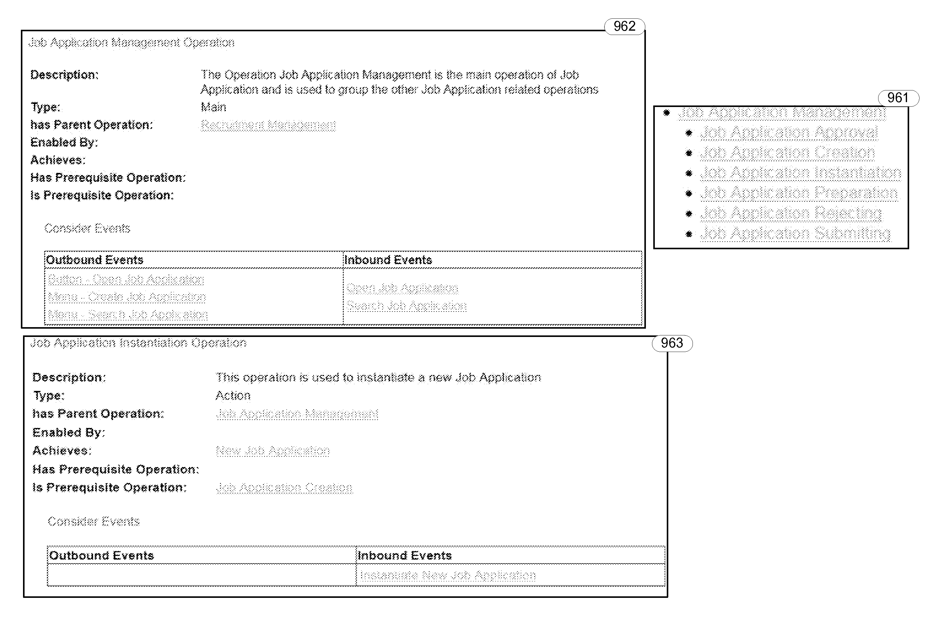
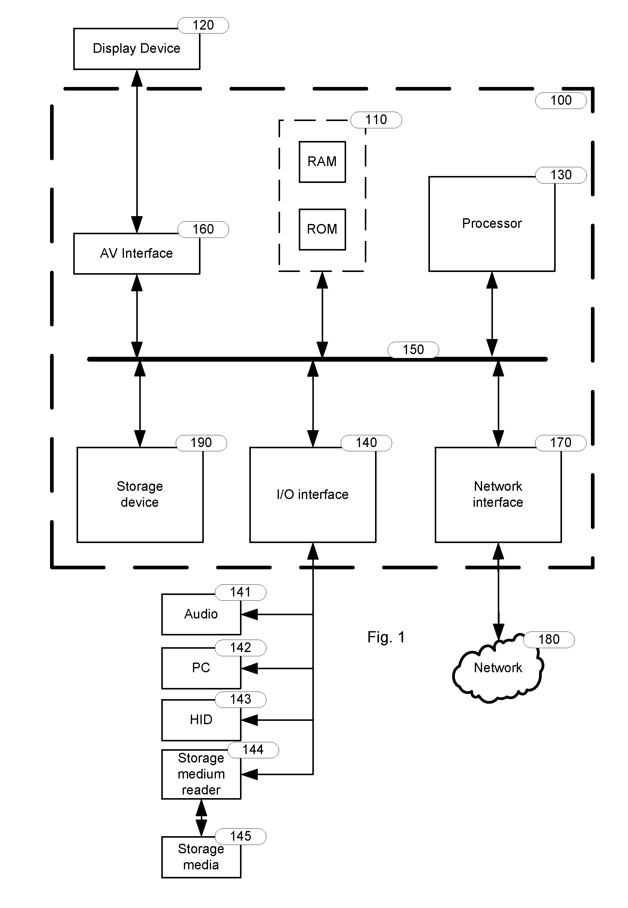
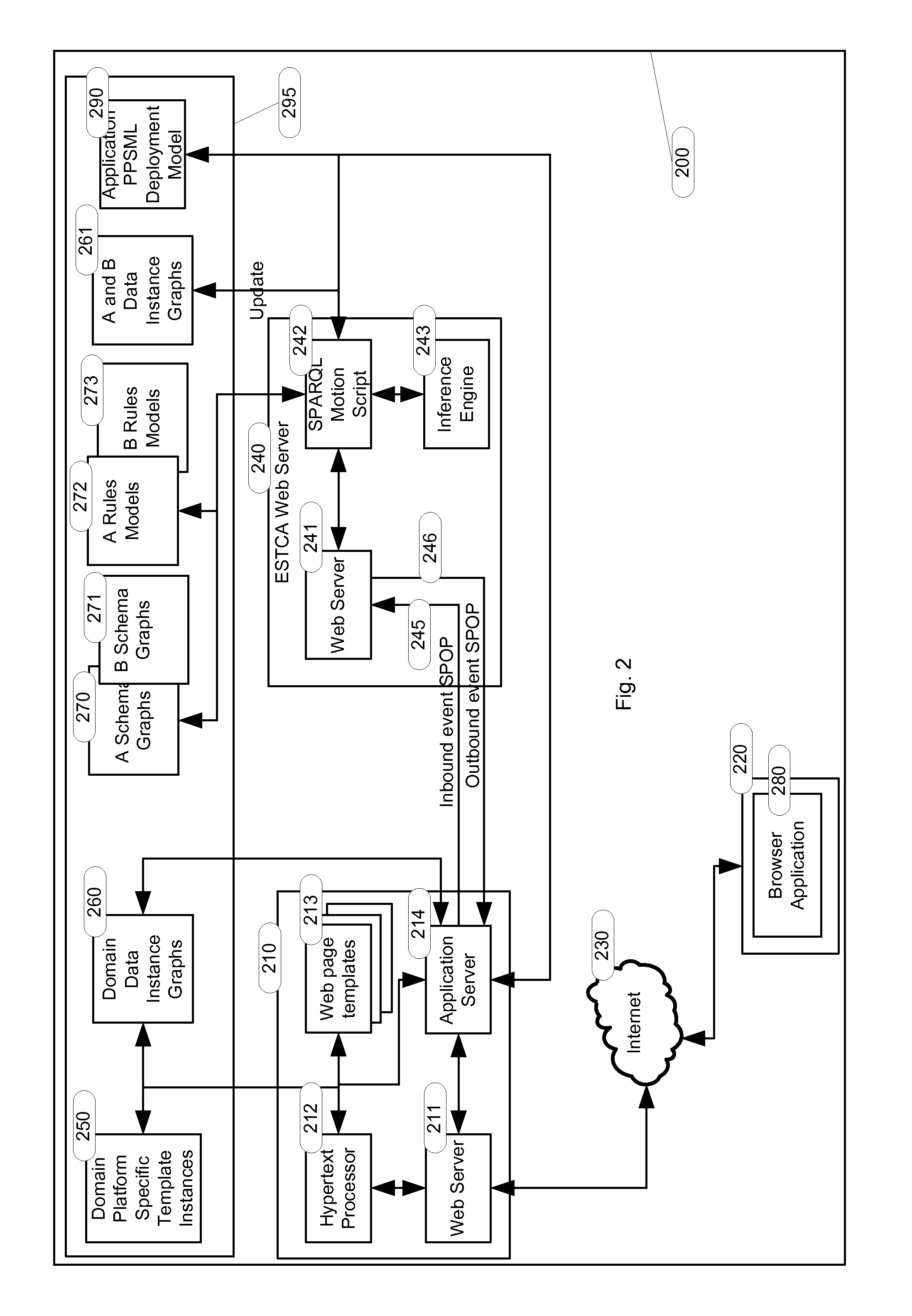
The present invention provides a method for state transitions of recursive state machines using a computer-readable carrier medium that contains computer program code. The method involves receiving event data representing an event in relation to a first object, first object data representing the first object, second object data representing a second object, and data representing a relationship between the second object and the first object. The method calculates a valid state transition based on the relationship between the second state and the first state. The invention also includes a computing device for state transitions of recursive state machines that receives and processes the event data, first object data, and second object data to calculate the valid state transition. The technical effects of the invention include improved efficiency in state transitioning and improved performance of computing devices for large systems involving human and automated components.

Problems solved by technology

However, not all of one company's modules are necessarily the “best of breed”; some vendors may specialise in particular areas (e.g., supply chain, or customer relationship) and produce superior products in their particular specialty.
This in turn raises the issue of integrating offerings from different vendors.
At this point, the attractiveness of “packaged software” brought to the fore a new issue in business automation strategy: the “make or buy” decision.
Wholly integrated solutions were typically expensive, while combining individual best-of-breed modules or developing in-house raised architecture, design and cost issues.
The lack of an established discipline for software construction has disastrous effects on software project costs and on the quality of results.
But there were no principles to guide reuse.
On the other hand, objects tend to partition a domain of interest and fail to capture features common to different domains.
However, this flexibility has strict limits: if the user introduces customisations, i.e., modifications which do not fit the prescribed extensions or configurations, the vendor offers no guarantee as to compatibility with future versions.
Also, because extensions and customisations are specific to a given package, the associated concepts are not portable across packages, and cannot support an enterprise-wide approach.
While ITIL and other accepted norms of Information Technology refer to services, and may provide guidance on their management, there was no accurate definition of a service as such.
IT Architects have long realised that they cannot devise sensible solutions without first having defined the business problem.
However, in the past this definition was done piecemeal, addressed a limited scope, and took the form of a collection of requirements often lacking any sort of internal structure.
The challenge of IT Architecture arises from the fact that Business Information Systems are complex systems, which embody several kinds of regularities at once.
Any notation designed to document one kind of regularity (e.g., process) may be incompatible with notations for other kinds.
Yet Enterprise Architecture still remains “headless”, inasmuch as the essential motivation for its existence is not established with adequate clarity and precision.
While several theories of business organisation are extant, there is no systematic approach to the discovery, analysis and definition of the architecture of a whole business endeavour.
In each, the elements associated with the definition of a business are little more than conceptual placeholders, lacking the clarity and precision of the more technical terms.
The major challenge to the construction of an adequate Business Architecture arises from the language practices within business.
While business people mostly understand each other in everyday practice, difficulties arise when attempting to apply formal methods.
Since the notation adopted here is natural language, we are doomed to failure unless we introduce usage conventions in the form of a Controlled Vocabulary, i.e., a set of chosen words associated with an agreement to use the words of the set according to specific semantic rules controlling their denotation.
But there are no directing principles for this specialisation, with the consequence of incompatibility among the work of different individual practitioners.
This situation raises a serious challenge to the modeller: in order to be applicable to this diversity of fact, the modelling artefacts must exhibit three kinds of invariance.
On the other hand, given that its application is restricted to processes, it has nothing to offer for scale invariance in other aspects (e.g., objects or capabilities).
The language itself has nothing specific to offer to guarantee scale invariance.
System failures have often been traced to a failure of communication between the business agencies expressing their need for functionality and the Information technologists who were charged with supplying that need.
It is not possible to find isomorphisms between those two worlds.
However, these ideas are still at the conceptual stage, and much R&D is required to bring them to a point where their effectiveness can be assessed.
Such cases are called discrepancies, and are the source of much of the systems' complexity.

Method used


Image

  • Computing device for state transitions of recursive state machines and a computer-implemented method for the definition, design and deployment of domain recursive state machines for computing devices of that type
  • Computing device for state transitions of recursive state machines and a computer-implemented method for the definition, design and deployment of domain recursive state machines for computing devices of that type
  • Computing device for state transitions of recursive state machines and a computer-implemented method for the definition, design and deployment of domain recursive state machines for computing devices of that type

Examples


embodiments

[1122]Reference throughout this specification to “one embodiment” or “an embodiment” means that a particular feature, structure or characteristic described in connection with the embodiment is included in at least one embodiment of the present invention. Thus, appearances of the phrases “in one embodiment” or “in an embodiment” in various places throughout this specification are not necessarily all referring to the same embodiment, but may. Furthermore, the particular features, structures or characteristics may be combined in any suitable manner, as would be apparent to one of ordinary skill in the art from this disclosure, in one or more embodiments.

[1123]Similarly it should be appreciated that in the above description of example embodiments of the invention, various features of the invention are sometimes grouped together in a single embodiment, figure, or description thereof for the purpose of streamlining the disclosure and aiding in the understanding of one or more of the vario...


PUM


Abstract

A computing device for state transitions of recursive state machines and a computer-implemented method for the definition, design and deployment of domain recursive state machines for computing devices of that type; such devices are intended for the simulation of large systems involving human and automated components, particularly the type generally called “Enterprise Applications”; such devices are also applicable to a much wider range of fields, such as cognitive modelling or robotics. The commonality between the computing device and the computer-implemented method is the Subject Predicate Object Protocol (SPOP) which is used to capture instructions by the computer-implemented method for the definition, design and deployment of recursive state machines and also is the protocol used by the computing device for state transitions of recursive state machines to communicate inbound and outbound events based on the captured instructions.

Description

TECHNICAL FIELD[0001]The present invention relates to the construction of an appliance that implements executable models of complex systems involving several disparate types of activity dynamics.[0002]It has been developed primarily for the simulation of large systems involving human and automated components, particularly the type generally called “Enterprise Applications”. However it is applicable to a much wider range of fields, such as cognitive modelling or robotics.[0003]The description that follows will make use of examples drawn from a Human Resources Application and an Enterprise Framework Application, however it can be used for any application.BACKGROUND ART[0004]Any reference to publications or acts cited in this specification is not an admission that the disclosures constitute common general knowledge in Australia or elsewhere.Enterprise Software History[0005]In the early days of computing, software was not thought of as an independent category of activity or product. In ...

Claims


Application Information

Patent Timeline
IPC IPC(8): G06F9/54G06F9/44
CPCG06F9/4428G06F9/542G06N5/025G06F9/4488G06F7/00
Inventor SCOMPARIM, GUILHERME
Owner PMDA SERVICES
Learn More