Artificial dielectric lens

a dielectric lens and dielectric technology, applied in the field of artificial dielectric lenses, can solve the problems of difficult to achieve or design the desired refractive index n arbitrarily with a material existing in the natural world, and achieve the effect of convenient arrangement of lenses, easy availability of materials, and low cos

Inactive Publication Date: 2015-06-18
IBARAKI UNIVERSITY
View PDF4 Cites 4 Cited by
  • Summary
  • Abstract
  • Description
  • Claims
  • Application Information

AI Technical Summary

Benefits of technology

[0011]According to this invention, the lens is formed by laminating the multiple conductive plate pieces such that the conductive plate pieces are arranged parallel to each other at the given intervals. This causes visible light to pass through the artificial dielectric lens. Thus, the artificial dielectric lens can be arranged in place by observing visible light, thereby facilitating arrangement of the lens in place. A wave is delayed and collected according to the parameters including the number of the groove portion, the width and the depth of the groove portion. Thus, the resultant artificial dielectric lens is allowed to have a desired refractive index. In addition, since the lens is configured using the conductive plate pieces of a simple structure, the lens can be configured without requiring highly accurate processing. And also since the conductive plate pieces are made of metal, the lens can be configured with easily available material without requiring a special material.

Problems solved by technology

Achieving or designing a desired refractive index n arbitrarily with a material existing in the natural world is not easy.

Method used


Image

  • Artificial dielectric lens
  • Artificial dielectric lens
  • Artificial dielectric lens

Examples


first embodiment

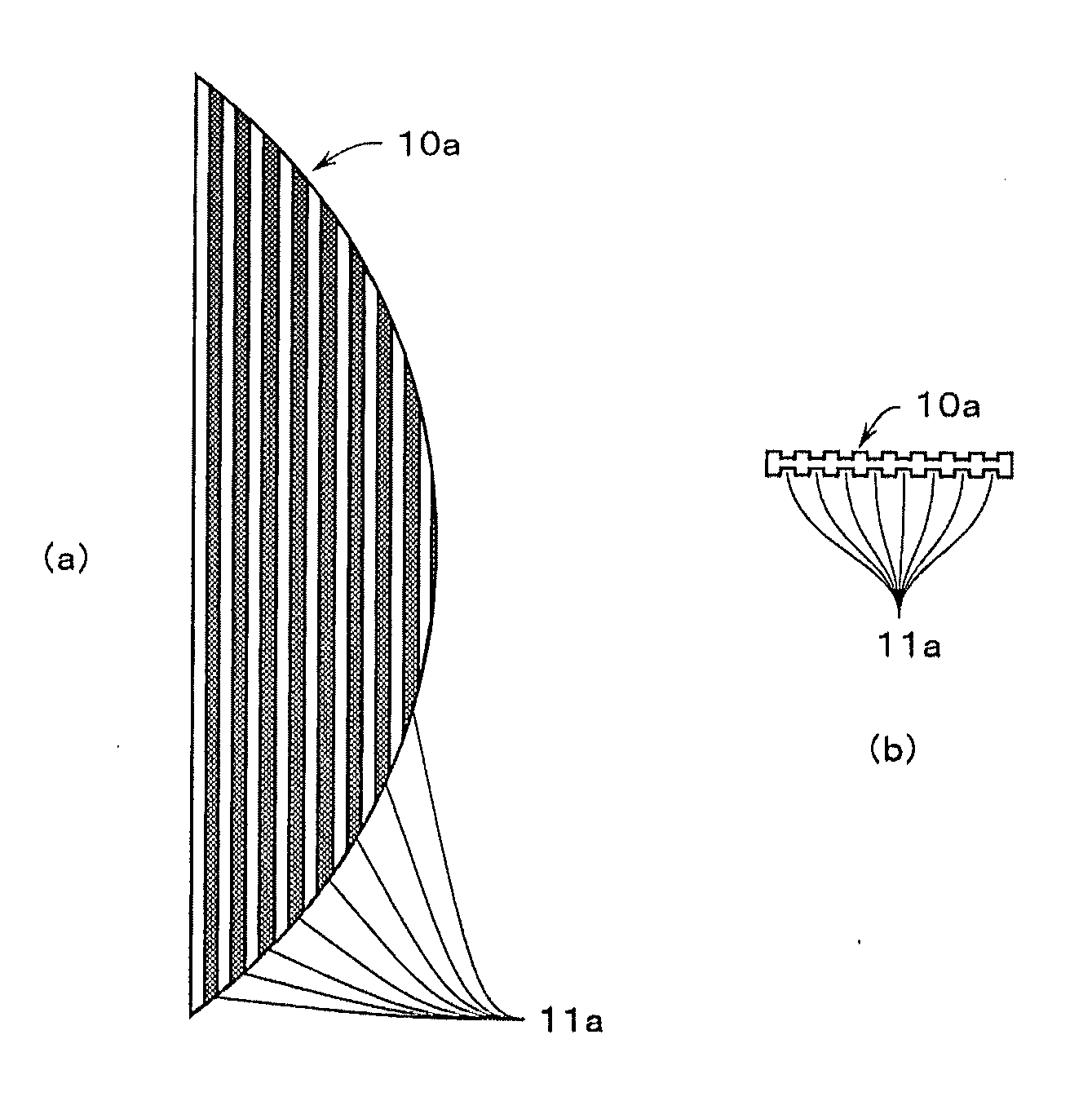
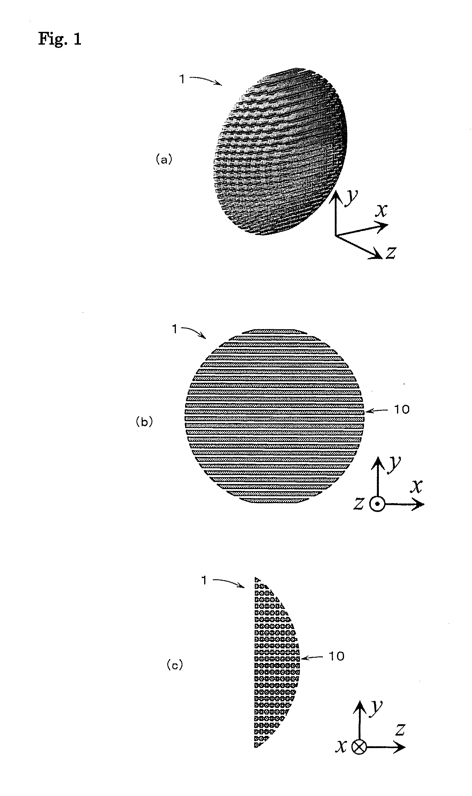
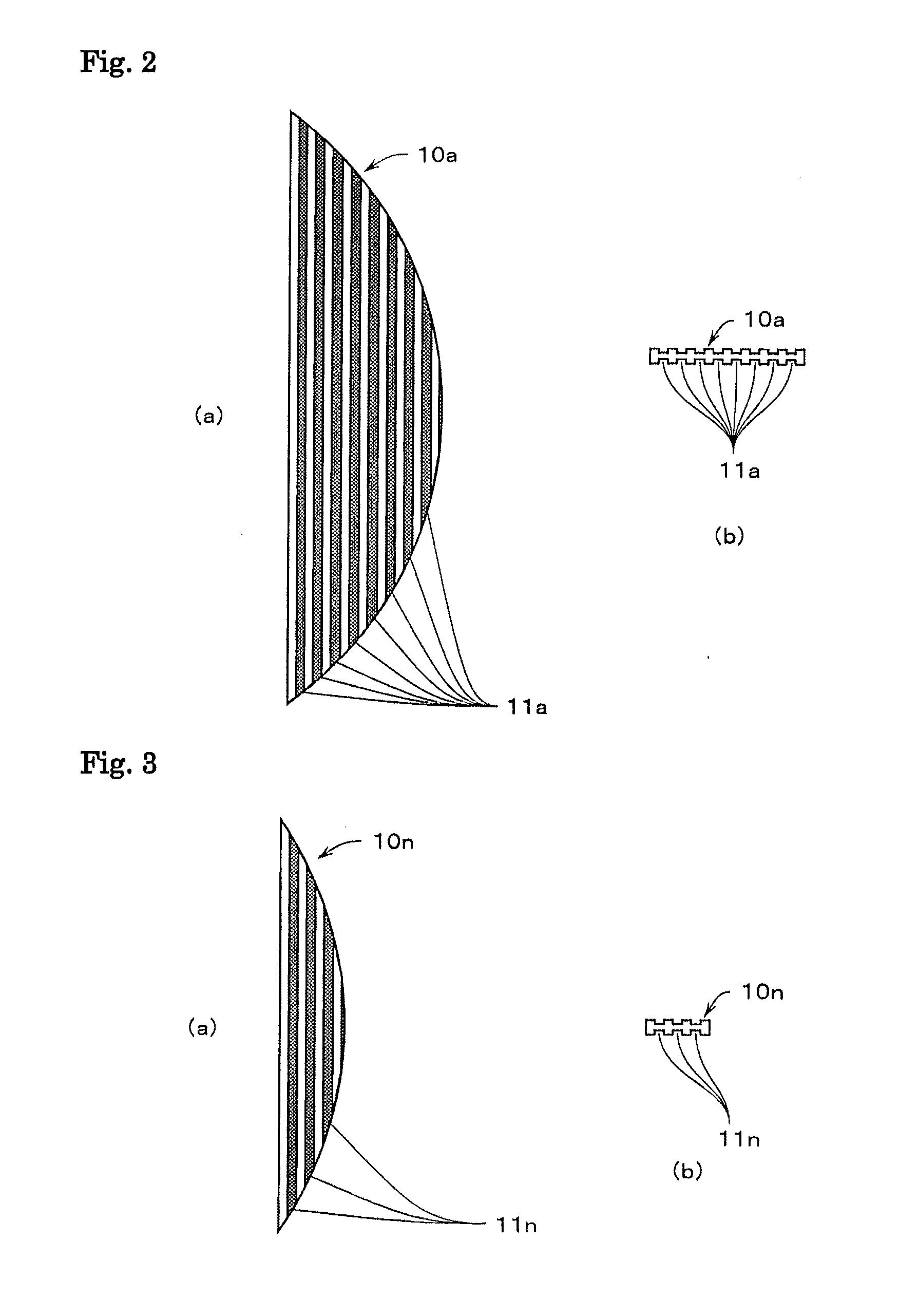
[0033]FIGS. 1(a), 1(b), and 1(c) are a perspective view, a front view, and a side view respectively showing the structure of a metal dielectric lens as an artificial dielectric lens of this invention.

[0034]As shown in these drawings, a metal dielectric lens 1 of this invention shown in these drawings is a circular lens with one side surface formed into a planar shape and an opposite side surface formed into a spherical shape. A z-axis is defined as an optical axis of the metal dielectric lens 1 and axes perpendicular to the z-axis are defined as an x-axis and a y-axis. An outer shape of multiple metal plate pieces 10 is such that the respective cross sections of the metal plate pieces 10 are parallel to x-z planes at given intervals of the lens along the y-axis from a lower edge to the center and from the center to an upper edge. The metal dielectric lens 1 is formed by laminating the multiple metal plate pieces 10 such that the metal plate pieces 10 are arranged parallel to the x-z...

second embodiment

[0057]FIGS. 14(a), 14(b), and 14(c) are a perspective view, a front view, and a side view respectively showing the configuration of a metal dielectric lens 3 as the artificial dielectric lens of this invention.

[0058]As shown in these drawings, the metal dielectric lens 3 of the second embodiment of this invention shown in these drawings is a circular lens with one side surface formed into a planar shape and an opposite side surface formed into a spherical shape. The z-axis is defined as an optical axis of the metal dielectric lens 3 and axes perpendicular to the z-axis are defined as the x-axis and the y-axis. An outer shape of multiple metal plate pieces 30 is such that the respective cross sections of the metal plate pieces 30 are parallel to the x-z planes at given intervals of the lens along the y-axis from a lower edge to the center and from the center to an upper edge. The metal dielectric lens 3 is formed by laminating the multiple metal plate pieces 30 such that the metal pl...

third embodiment

[0060]FIGS. 15(a), 15(b), and 15(c) are a perspective view, a front view, and a side view respectively showing the configuration of a metal dielectric lens 4 as the artificial dielectric lens of this invention.

[0061]As shown in these drawings, the metal dielectric lens 4 of the third embodiment of this invention shown in these drawings is a cylindrical lens with one side surface formed into a planar shape and an opposite side surface formed into a spherical shape. The z-axis is defined as an optical axis of the metal dielectric lens 4 and axes perpendicular to the z-axis are defined as the x-axis and the y-axis. An outer shape of multiple metal plate pieces 40 is such that the respective cross sections of the metal plate pieces 40 are parallel to the x-z planes at given intervals of the lens along the y-axis from a lower edge to the center and from the center to an upper edge. The metal dielectric lens 4 is formed by laminating the multiple metal plate pieces 40 such that the metal ...


PUM


Abstract

A z-axis is defined as an optical axis and axes perpendicular to the z-axis are defined as an x-axis and a y-axis. Multiple metal plate pieces each have multiple groove portions formed in the direction of the x-axis. An outer shape of the metal plate pieces are such that the respective cross sections of the metal plate pieces are parallel to x-z planes at given intervals of a lens along the y-axis from a lower edge to a center and from the center to an upper edge. A metal dielectric lens is formed by laminating the metal plate pieces such that the metal plate pieces are arranged parallel to the x-z planes at the given intervals. Thus a refractive index responsive to the number of the groove portions, and the width and the depth of the groove portion can be obtained. A resultant structure causes visible light to pass therethrough.

Description

TECHNICAL FILED[0001]This invention relates to an artificial dielectric lens that can be arranged in place easily and can obtain a desired refractive index.BACKGROUND ART[0002]A terahertz electromagnetic wave as a short-wavelength electromagnetic wave has a frequency from 0.1 to 10 THz (wavelength from 30 to 3000 μm). This wavelength is substantially the same as a range from the wavelength of a far-infrared wave to that of a millimeter wave. The terahertz electromagnetic wave exists in a frequency range between the frequency of “light” and that of a “millimeter wave.” Thus, the terahertz electromagnetic wave has both an ability to identify an object with a spatial resolution as high as that of light and an ability to pass through a substance like a millimeter wave. An electromagnetic wave in the terahertz wave band has not been explored so far. Meanwhile, application of this electromagnetic wave for example to characterization of a material has been considered that is to be achieved...

Claims


Application Information

Patent Timeline
Patent Type & Authority Applications(United States)
IPC IPC(8): G02B1/00G02B13/14
CPCG02B13/14G02B1/002H01Q15/10H01Q15/04
Inventor SUZUKI, TAKEHITO
Owner IBARAKI UNIVERSITY
Why Eureka
Try Eureka