Turbine component patch delivery system

a technology for components and turbines, applied in the field of turbine component patch delivery systems, can solve the problems of affecting the operation efficiency and affecting the durability of the machine, and the underlying cmc may be subject to cavitation

Inactive Publication Date: 2015-06-25
GENERAL ELECTRIC CO
View PDF29 Cites 19 Cited by
  • Summary
  • Abstract
  • Description
  • Claims
  • Application Information

AI Technical Summary

Problems solved by technology

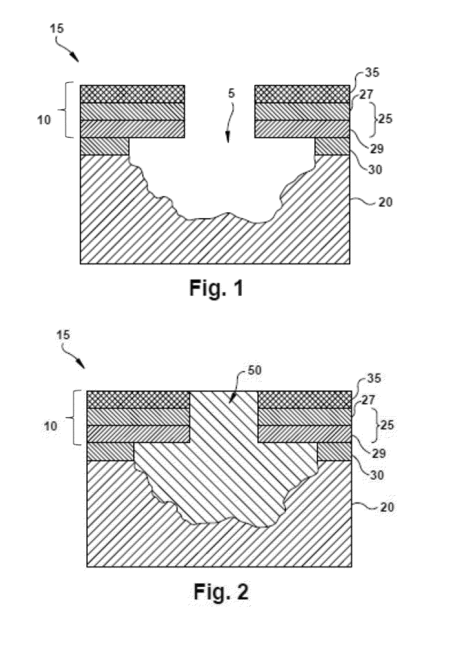
Furthermore, if an EBC experiences a localized spall or a pinhole defect, the underlying CMC may be subject to cavitation resulting from water vapor induced volatilization and subsequent surface recession during service.
If allowed to grow unmitigated, such cavities may reduce the load-bearing capability of the component, disrupt airflow, or even progress to through-thickness holes that lead to ingestion of combustion gases or leakage of high-pressure cooling air, thus adversely affecting operating efficiency and durability of the machine.

Method used


Image

  • Turbine component patch delivery system
  • Turbine component patch delivery system
  • Turbine component patch delivery system

Examples


Embodiment Construction

[0018]One or more specific embodiments of the present invention will be described below. In an effort to provide a concise description of these embodiments, all features of an actual implementation may not be described in the specification. It should be appreciated that in the development of any such actual implementation, as in any engineering or design project, numerous implementation-specific decisions must be made to achieve the developers' specific goals, such as compliance with system-related and business-related constraints, which may vary from one implementation to another. Moreover, it should be appreciated that such a development effort might be complex and time consuming, but would nevertheless be a routine undertaking of design, fabrication, and manufacture for those of ordinary skill having the benefit of this disclosure.

[0019]When introducing elements of various embodiments of the present invention, the articles “a,”“an,”“the,” and “said” are intended to mean that ther...


PUM

PropertyMeasurementUnit
thicknessaaaaaaaaaa
surface temperaturesaaaaaaaaaa
total thicknessaaaaaaaaaa

Abstract

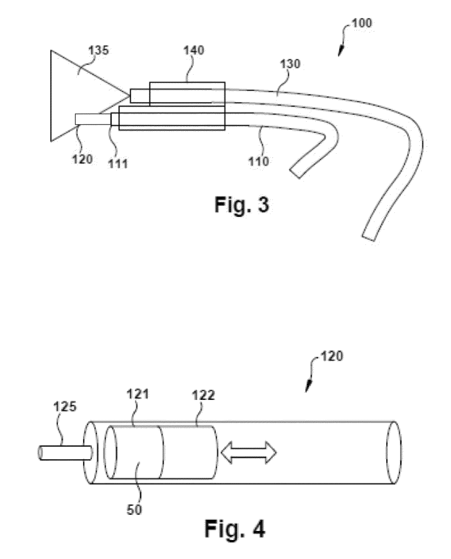
A turbine component patch delivery system can include a support arm and a deposition tool supported by the support arm. The deposition tool can include a reservoir configured to house a turbine component patch material and a dispenser configured to dispense the turbine component patch material from the reservoir onto a surface of a turbine component.

Description

CROSS REFERENCE TO RELATED APPLICATIONS[0001]This application is a continuation-in-part to U.S. patent application Ser. No. 14 / 134,257, filed on Dec. 19, 2013, which is fully incorporated by reference and made a part hereof.STATEMENT REGARDING FEDERALLY SPONSORED RESEARCH & DEVELOPMENT[0002]This invention was partially made with government support under government contract No. DE-FC26-05NT42643 awarded by the Department of Energy. The government has certain rights to this invention.BACKGROUND OF THE INVENTION[0003]The subject matter disclosed herein relates to patch repair and, more specifically, environmentally resistant patches for filling voids in silicon-containing components, such as silicon carbide (SiC) based ceramic matrix composites (CMCs).[0004]Environmental barrier coatings (EBCs) protect gas turbine components fabricated from silicon-containing substrates from exposure to potentially harmful chemical environments in service. Examples of silicon-containing substrates incl...

Claims


Application Information

Patent Timeline
Patent Type & Authority Applications(United States)
IPC IPC(8): B29C73/02
CPCB29C73/025B29L2031/08B29K2103/04
Inventor KOLVICK, SANDRA BEVERLYLIPKIN, DON MARKLOMAS, JONATHAN MATTHEWREID, THOMAS ROBERTKITTLESON, JACOB JOHN
Owner GENERAL ELECTRIC CO
Why Eureka
Try Eureka