
MEMS sensor module and MEMS sensor package module

a sensor module and sensor technology, applied in the direction of acceleration measurement in multiple dimensions, acceleration measurement using interia forces, instruments, etc., can solve the problems of limited degree of freedom and difficulty in thinness implementation, and achieve the effect of maximizing driving performan

Inactive Publication Date: 2015-06-25
SAMSUNG ELECTRO MECHANICS CO LTD
View PDF3 Cites 2 Cited by
  • Summary
  • Abstract
  • Description
  • Claims
  • Application Information

AI Technical Summary

Benefits of technology

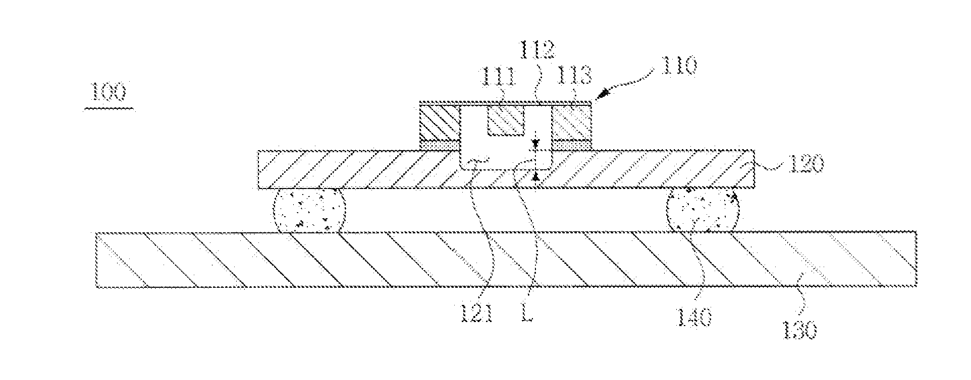
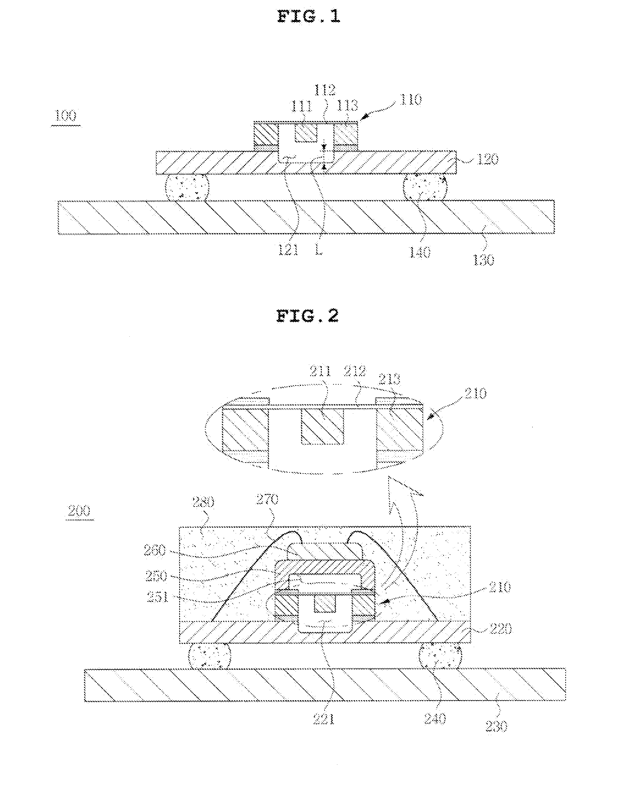
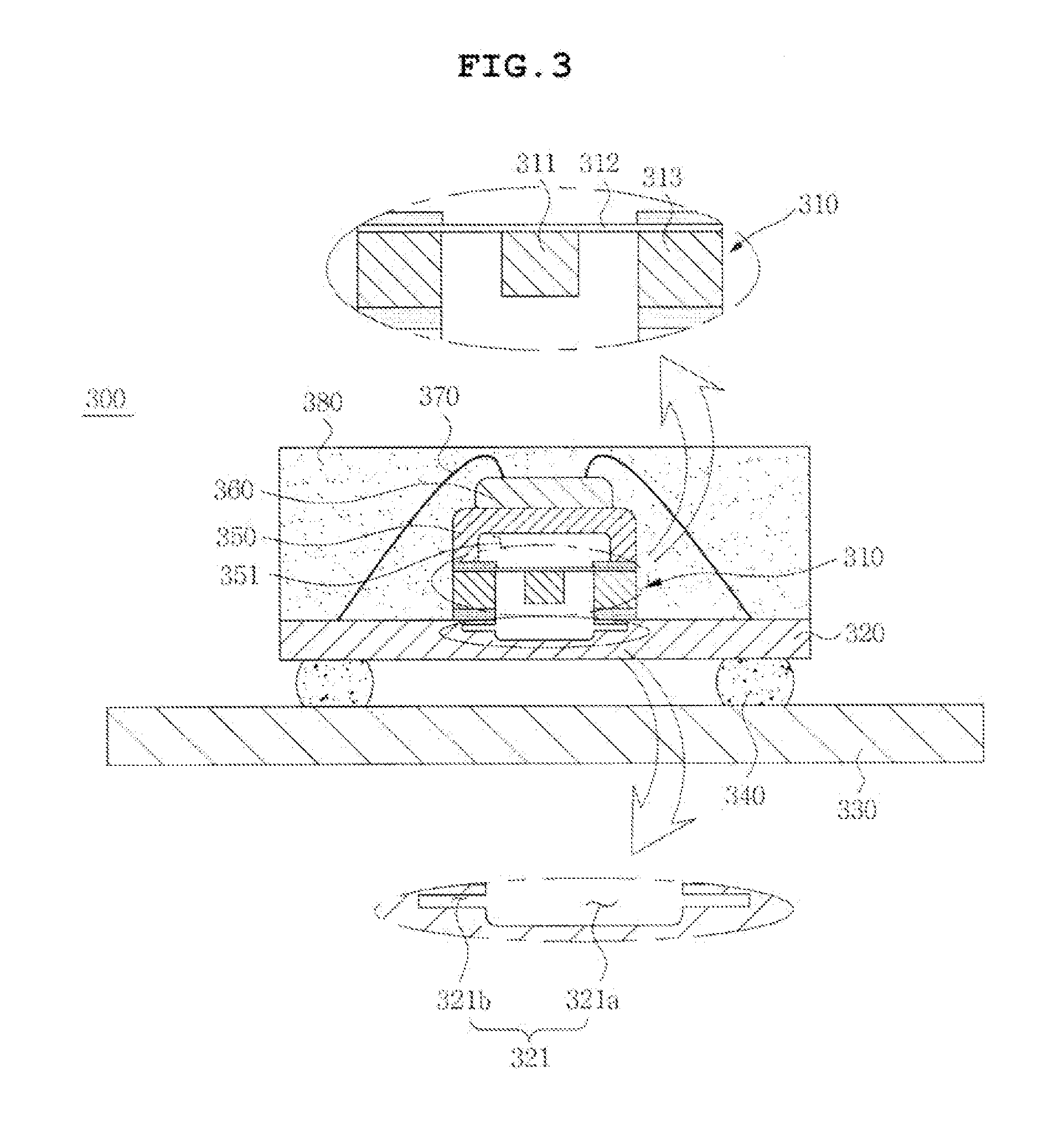
The invention aims to provide a thin MEMS sensor module that has improved driving performance by designing a cavity in the substrate where the sensor part is connected. This eliminates the need for a separate sensor part cap and maximizes the performance of the sensor.

Problems solved by technology

Thus, since the MEMS sensor, as described, for example, in U.S. Patent Publication No. 2009 / 0232918, forms a cavity by a cap adjusting a size of a mass body or covering a sensor part in order to form the cavity, a degree of freedom thereof is limited and it is difficult to implement thinness.

Method used


Image

  • MEMS sensor module and MEMS sensor package module
  • MEMS sensor module and MEMS sensor package module
  • MEMS sensor module and MEMS sensor package module

Examples


Embodiment Construction

:

[0028]Advantages and features of the present invention and methods of accomplishing the same will be apparent by referring to embodiments described below in detail in connection with the accompanying drawings. However, the present invention is not limited to the embodiments disclosed below and may be implemented in various different forms. The embodiments are provided only for completing the disclosure of the present invention and for fully representing the scope of the present invention to those skilled in the art.

[0029]For simplicity and clarity of illustration, the drawing figures illustrate the general manner of construction, and descriptions and details of well-known features and techniques may be omitted to avoid unnecessarily obscuring the discussion of the described embodiments of the invention. Additionally, elements in the drawing figures are not necessarily drawn to scale. For example, the dimensions of some of the elements in the figures may be exaggerated relative to o...


PUM


Abstract

Embodiments of the invention provide a micro electro mechanical system (MEMS) sensor module, including a sensor, a substrate connected to the sensor, and an external board connected to the substrate by a conductive connector. The substrate is provided with a cavity so as to be opposite to the sensor.

Description

CROSS REFERENCE TO RELATED APPLICATION[0001]This application claims the benefit of and priority under 35 U.S.C. §119 to Korean Patent Application No. KR 10-2013-0161560, entitled “MEMS SENSOR MODULE AND MEMS SENSOR PACKAGE MODULE,” filed on Dec. 23, 2013, which is hereby incorporated by reference in its entirety into this application.BACKGROUND[0002]1. Field of the Invention[0003]The present invention to a micro electro mechanical system (MEMS) sensor module and a MEMS sensor package module.[0004]2. Description of the Related Art[0005]Generally, a MEMS sensor, for example, a multi-axis acceleration sensor or a multi-axis angular velocity sensor is used in various applications, for example, for a vehicle, an airplane, a mobile communication terminal, a toy, as non-limiting examples. The MEMS sensor has been developed for high performance and miniaturization in order to detect fine acceleration.[0006]A device including the MEMS sensor is very sensitive to a change in external stress.[...

Claims


Application Information

Patent Timeline
Patent Type & Authority Applications(United States)
IPC IPC(8): G01C19/5705G01P15/09
CPCG01P15/0922G01C19/5705G01P15/123G01P15/18G01C19/5783B81B7/02B81B3/00G01P15/08G01P3/44
Inventor JEUNG, WON KYULEE, JUNG WONSONG, JONG HYEONG
Owner SAMSUNG ELECTRO MECHANICS CO LTD
Learn More