

Electro-optical apparatus and electronic apparatus
- Summary
- Abstract
- Description
- Claims
- Application Information
AI Technical Summary
Benefits of technology
Problems solved by technology
Method used
Image

Examples
first embodiment
Overview of Virtual Image Display Device
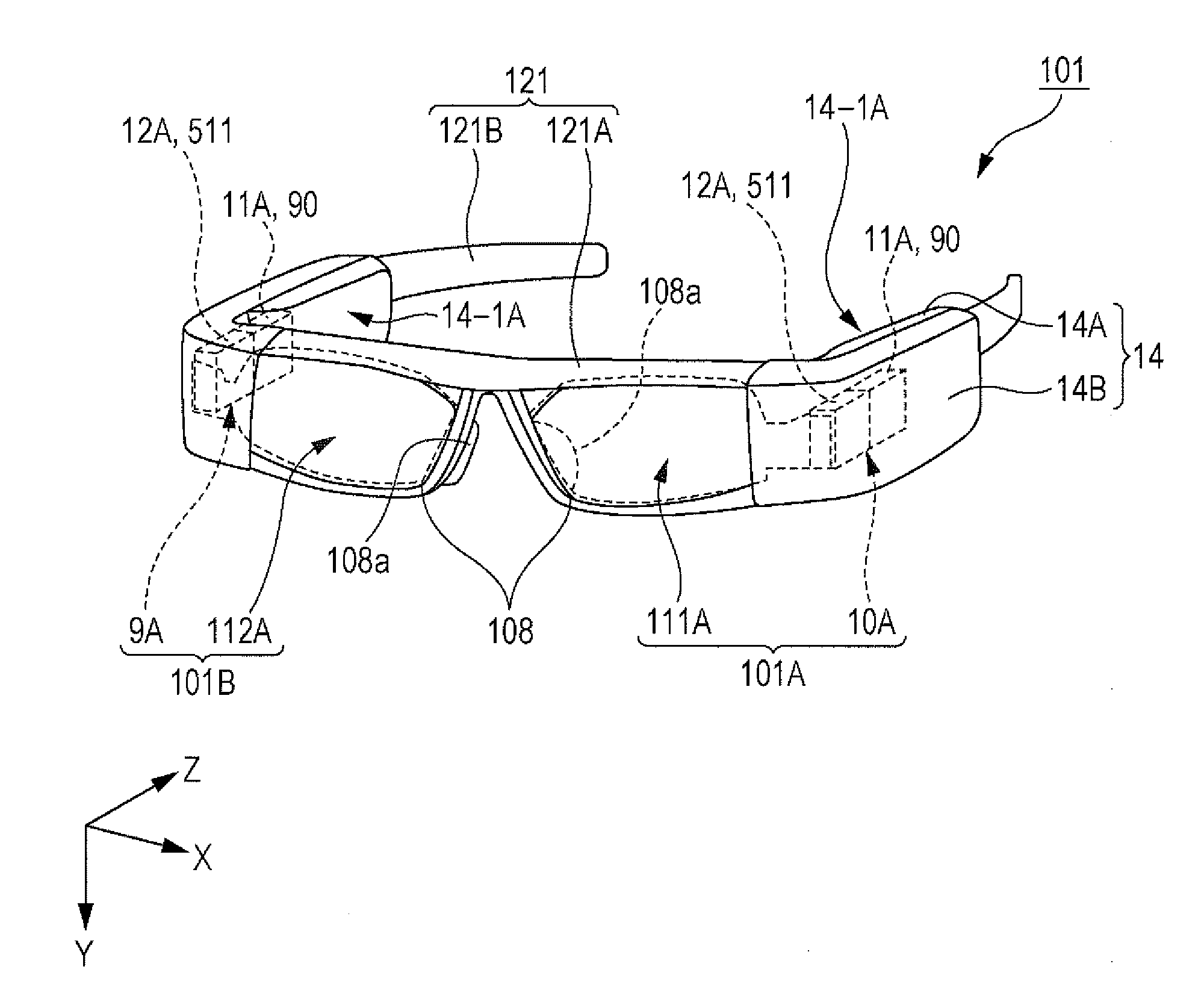
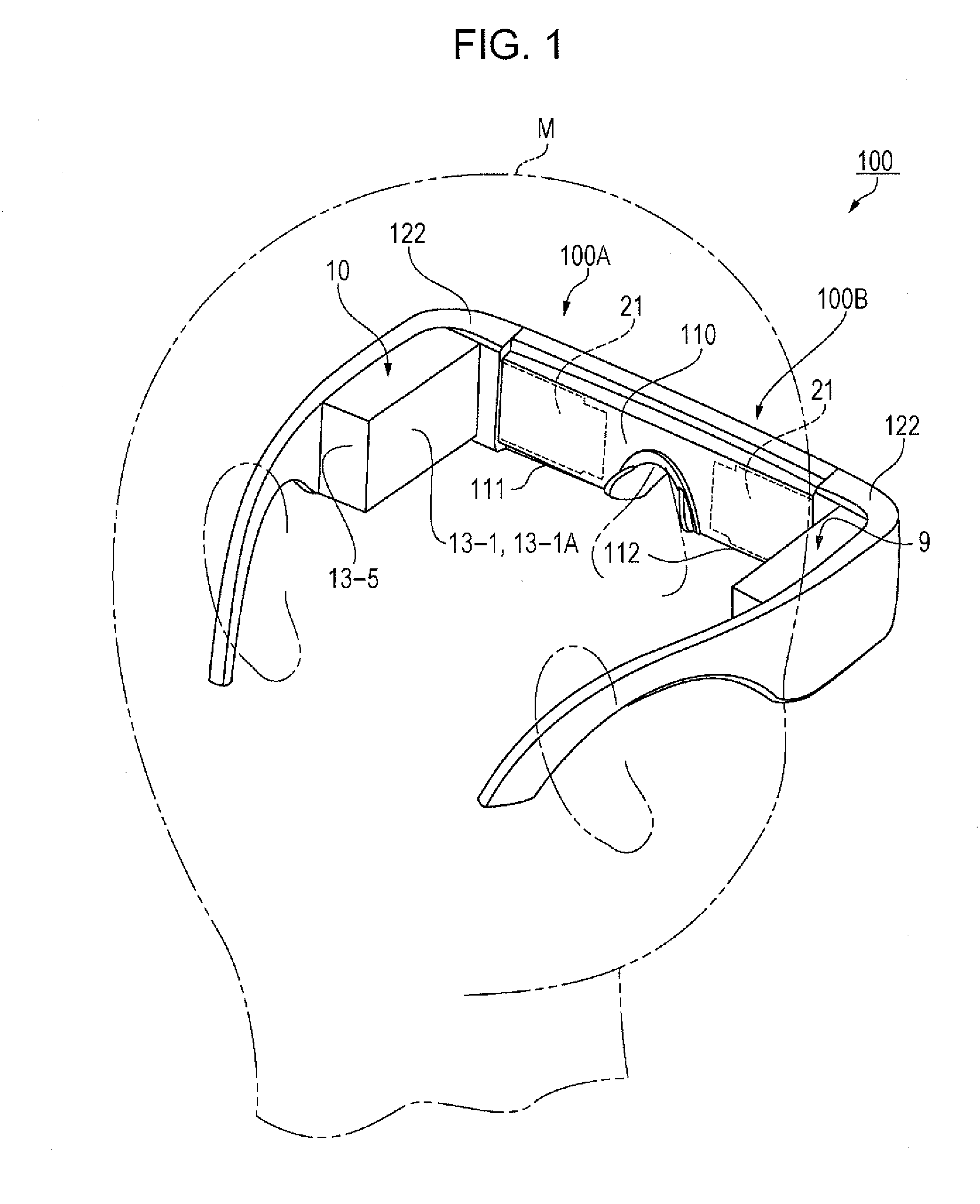
[0081]A virtual image display device 100 according to a first embodiment is a Head-Mounted Display (HMD) Device which is an example of an “electronic apparatus”, has an appearance like glasses, and is mounted on the head of a human body. A wearer M, on which the virtual image display device 100 is mounted, can recognize image light based on a virtual image using the virtual image display device 100. Further, the virtual image display device 100 has a see-through function. Accordingly, the wearer M can simultaneously observe the virtual image, generated by the virtual image display device 100, and external world image.
[0082]FIG. 1 is a schematic diagram illustrating the configuration of the virtual image display device according to the embodiment. First, the overview of the virtual image display device 100 will be described with reference to FIG. 1.
[0083]As shown in FIG. 1, the virtual image display device 100 includes an optical panel 110 whic...
second embodiment
[0174]FIG. 7A is a diagram corresponding to FIG. 3A, and is a schematic cross-sectional diagram illustrating the configuration of an image forming device according to a second embodiment. FIG. 7B is a schematic plan diagram illustrating the image forming device viewed from a direction which is perpendicular to FIG. 7A, that is, a schematic plan diagram illustrating the image forming device viewed from the Z(−) direction.
[0175]The main different point between an image forming device 10 according to the embodiment and the image forming device 10 according to the first embodiment is that a wall 13-4 is provided on the side of the housing 122, and a third space 17 is formed between the image display device 11 and the housing 122.
[0176]Hereinafter, the different point between the image forming device 10 according to the embodiment and the image forming device 10 according to the first embodiment will be mainly described with reference to FIGS. 7A and 7B. In addition, the same reference n...
third embodiment
[0190]FIG. 8 is a schematic diagram illustrating the configuration of a smart watch according to a third embodiment. FIG. 9 is a schematic cross-sectional diagram illustrating a display unit taken along a line IX-IX of FIG. 8.
[0191]Hereinafter, the overview of a smart watch 200 according to the embodiment will be described with reference to FIGS. 8 and 9.
[0192]The smart watch 200 is an example of an “electronic apparatus”, and is a wearable watch which has a function of a computer, a watch, or the like. The smart watch 200 is worn on the arm of the wearer M, and includes a display unit 201 which has a function to input and process data and a function to display the data, and a main body unit 202 which has a function for wireless communication and a function to process the data, as shown in FIG. 8.
[0193]Meanwhile, the display unit 201 is an example of an “electro-optical apparatus”.
[0194]The display unit 201 displays icons indicative of various processes, time (not shown in the drawi...
PUM
 Abstract
Description
Claims
Application Information