
Substrate processing apparatus

Active Publication Date: 2015-06-25
TOKYO ELECTRON LTD
View PDF9 Cites 195 Cited by
  • Summary
  • Abstract
  • Description
  • Claims
  • Application Information

AI Technical Summary

Benefits of technology

The invention aims to provide a device for processing substrates that can accurately measure the pressure in the chamber where the processing takes place.

Problems solved by technology

The generated deposit adheres on an inner wall of the chamber, and becomes a cause of generating dusts such as particles.

Method used


Image

  • Substrate processing apparatus
  • Substrate processing apparatus
  • Substrate processing apparatus

Examples


Embodiment Construction

[0016]A description is given below of embodiments of the present invention, with reference to accompanying drawings. Note that elements having substantially the same functions or features maybe given the same reference numerals and overlapping descriptions thereof may be omitted.

[0017][Overall Configuration of Substrate Processing Apparatus]

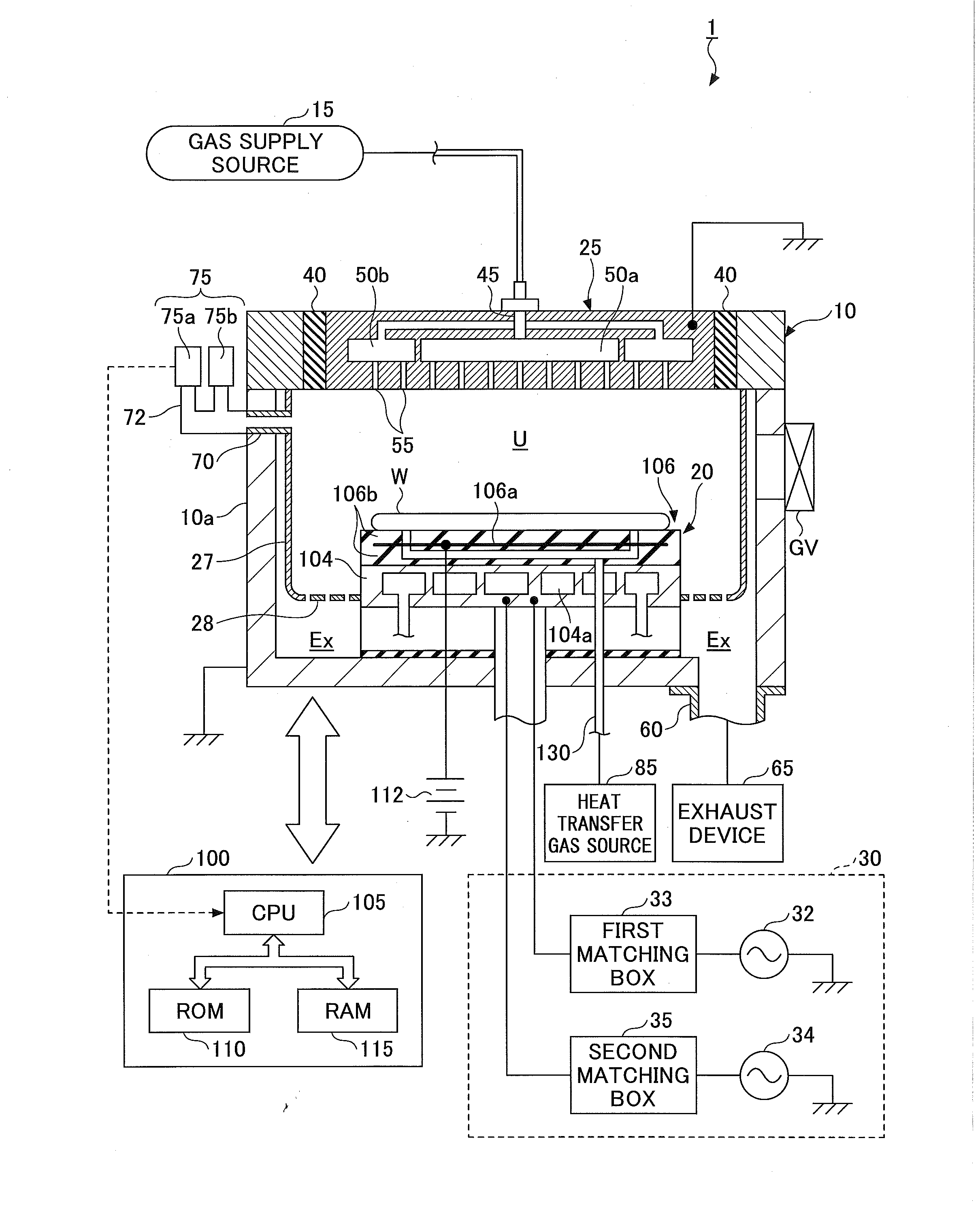
[0018]To begin with, a description is given below by citing an example of a substrate processing apparatus according to an embodiment of the present invention. FIG. 1 is a vertical cross-sectional view of the substrate processing apparatus according to the embodiment of the present invention. The substrate processing apparatus 1 of the embodiment includes a chamber 10 made of a conductive material such as aluminum or the like. The chamber 10 is electrically grounded.

[0019]At a location close to a side wall 10a of the chamber 10, a deposition shield 27, which is coated with aluminum or alumite, or coated with magnesium oxide (MgO), yttria (Y2O3) o...


PUM

PropertyMeasurementUnit
Flow rateaaaaaaaaaa
Electrical conductanceaaaaaaaaaa

Abstract

A substrate processing apparatus includes a chamber including a process chamber for performing a process on a substrate by a gas introduced thereto and an exhaust chamber for evacuating the gas in the process chamber, a shield member for separating the process chamber from the exhaust chamber provided in at least a part of a neighborhood of a side wall of the chamber, and a hollow relay member penetrating through the shield member for communicating the chamber with a pipe connected to a pressure gauge outside the chamber. The relay member is configured to receive a first gas flowing from the chamber into the relay member. The first gas has a first conductance. The first conductance is greater than a second conductance of a second gas flowing from the exhaust chamber into a gap between the relay member and the side wall of the chamber.

Description

CROSS-REFERENCE TO RELATED APPLICAITONS[0001]This patent application is based upon and claims the benefit of priority of Japanese Patent Application No. 2013-262207, filed on Dec. 19, 2013, the entire contents of which are incorporated herein by reference.BACKGROUND OF THE INVENTION[0002]1. Field of the Invention[0003]The present invention relates to a substrate processing apparatus.[0004]2. Description of the Related Art[0005]A substrate processing apparatus includes a chamber including a process chamber for performing a desired process such as an etching on a substrate by an introduced gas, and an exhaust chamber for evacuating a gas in the process chamber. A deposit is generated accompanying the etching process. The generated deposit adheres on an inner wall of the chamber, and becomes a cause of generating dusts such as particles.[0006]Therefore, a deposition shield is provided near the inner wall of the chamber, and the inner wall is covered with the deposition shield in order ...

Claims


Application Information

Patent Timeline
IPC IPC(8): H01J37/32
CPCH01J37/32651H01J2237/334H01J37/32458H01J37/32091H01J37/32477
Inventor SASAKI, NOBUTAKAKITAZAWA, TAKASHIYOSHIMURA, AKIHIRO
Owner TOKYO ELECTRON LTD
Features
  • Generate Ideas
  • Intellectual Property
  • Life Sciences
  • Materials
  • Tech Scout
  • Unparalleled Data Quality
  • Higher Quality Content
  • 60% Fewer Hallucinations
Learn More