

Wireless charger having moveable transimitter coil
- Summary
- Abstract
- Description
- Claims
- Application Information
AI Technical Summary
Benefits of technology
Problems solved by technology
Method used
Image

Examples
Embodiment Construction
[0018]Reference will now be made in detail to the preferred embodiment of the present invention.
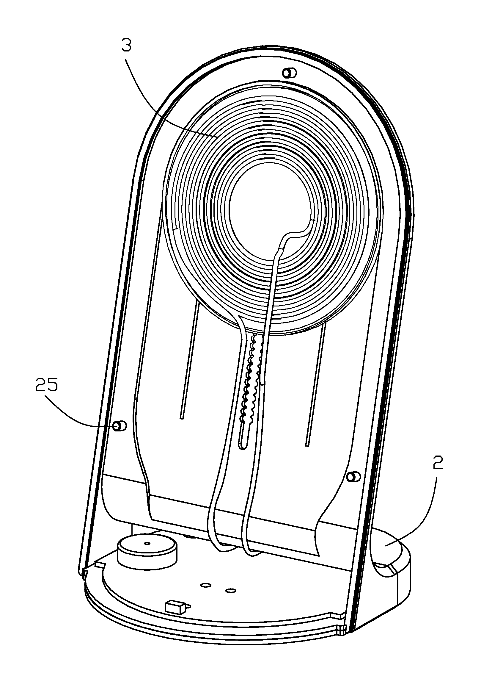
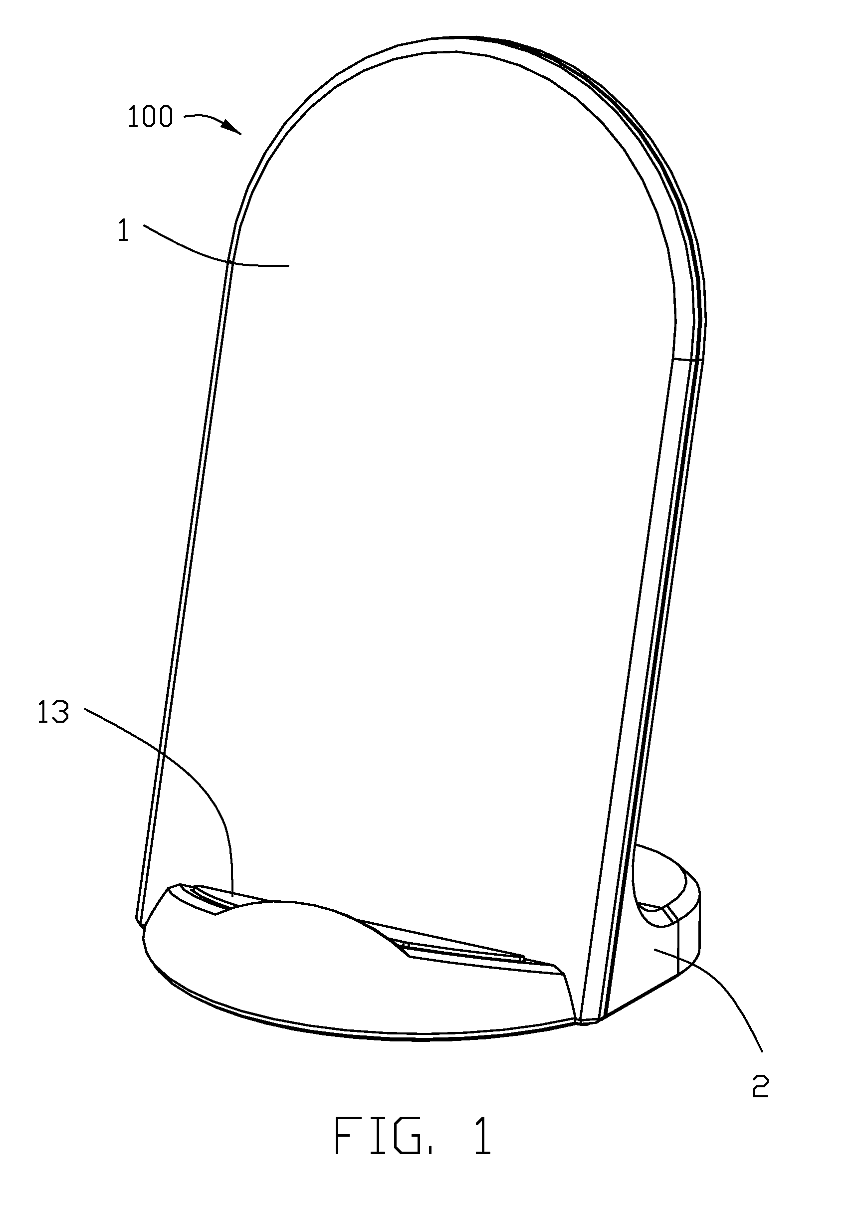
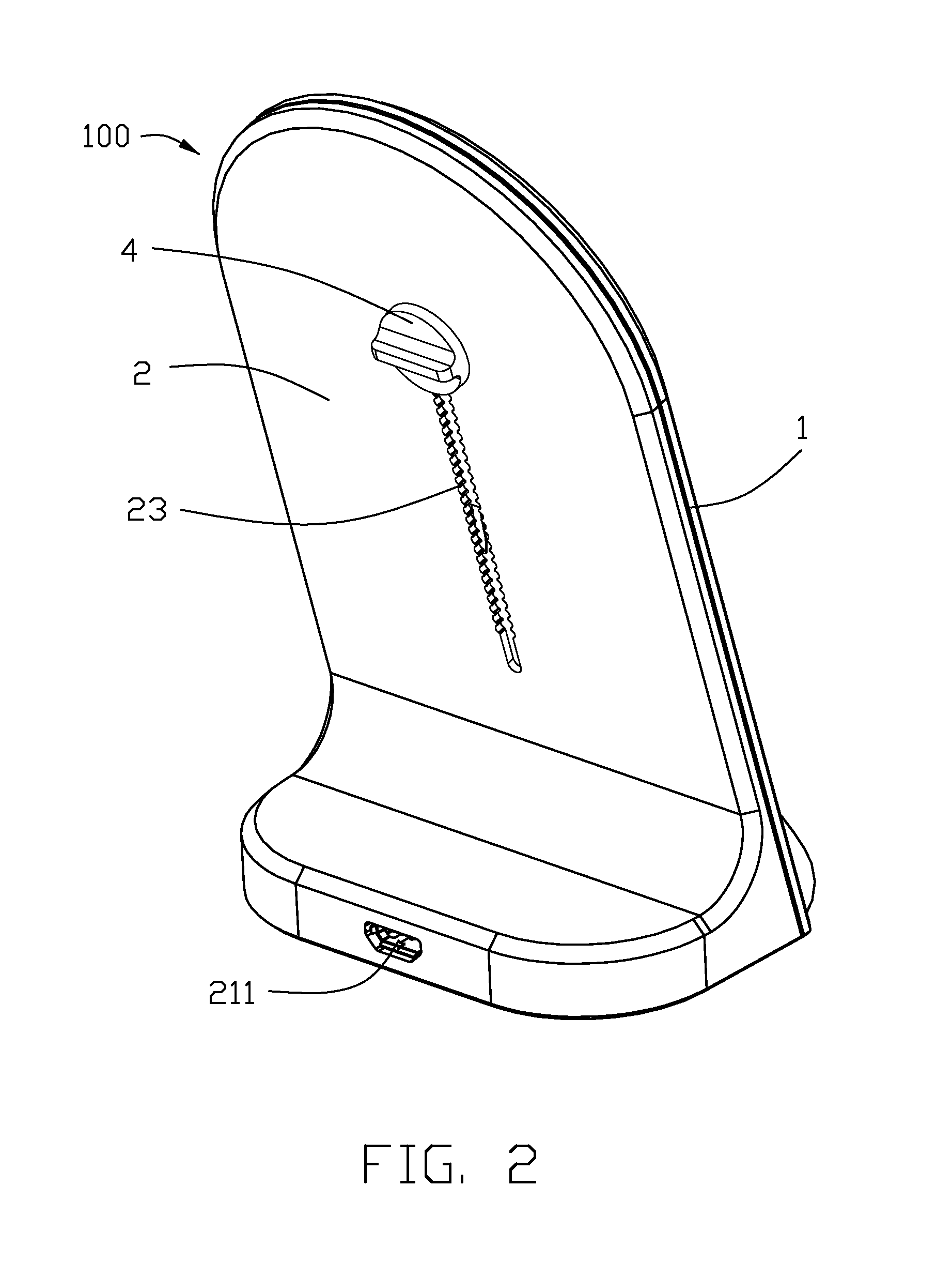
[0019]Referring to FIGS. 1-10, a wireless charger 100 according to the present invention is shown. The wireless charger 100 is used to charge a portable electronic device 200, which has a receiver coil (not shown). The wireless charger 100 includes a front body 1, a rear body 2, a transmitter coil assembly 3, and a shaft 4. The front body 1 is used to support the portable electronic device. The transmitter coil assembly 3 is used to inductively charge the receiver coil of portable electronic device 200. The transmitter coil assembly 3 and the receiver coil form a transformer therebetween for a wireless power transmission between the wireless charger 100 and the portable electronic device 200. The shaft 4 could drive the transmitter coil assembly 3 to align with the receiver coil of portable electronic device 200.
[0020]Referring to FIGS. 4-5, the front body 1 includes a platform portion 11...
PUM
 Abstract
Description
Claims
Application Information