Supercharge Your Innovation With Domain-Expert AI Agents!

Fishing reel

a reel and reel technology, applied in the field of fishing reels, can solve the problems of shortened flying distance of terminal tackles, and achieve the effect of stably winding a fishing line and reducing the resistance of winding

Active Publication Date: 2015-07-09
DAIWA SEIKO CORPORATION
View PDF18 Cites 5 Cited by
  • Summary
  • Abstract
  • Description
  • Claims
  • Application Information

AI Technical Summary

Benefits of technology

The invention is a fishing reel that has a guide body for the fishing line that is easy to replace, reduces resistance when the line is unwound, and keeps the line stable.

Problems solved by technology

Incidentally, the above-mentioned fishing line guide body has a problem in that, for example, a flying distance of a terminal tackle may be shortened since resistance is generated due to the contact between a fishing line and the fishing line guide body when the terminal tackle is cast.

Method used


Image

  • Fishing reel
  • Fishing reel
  • Fishing reel

Examples


first embodiment

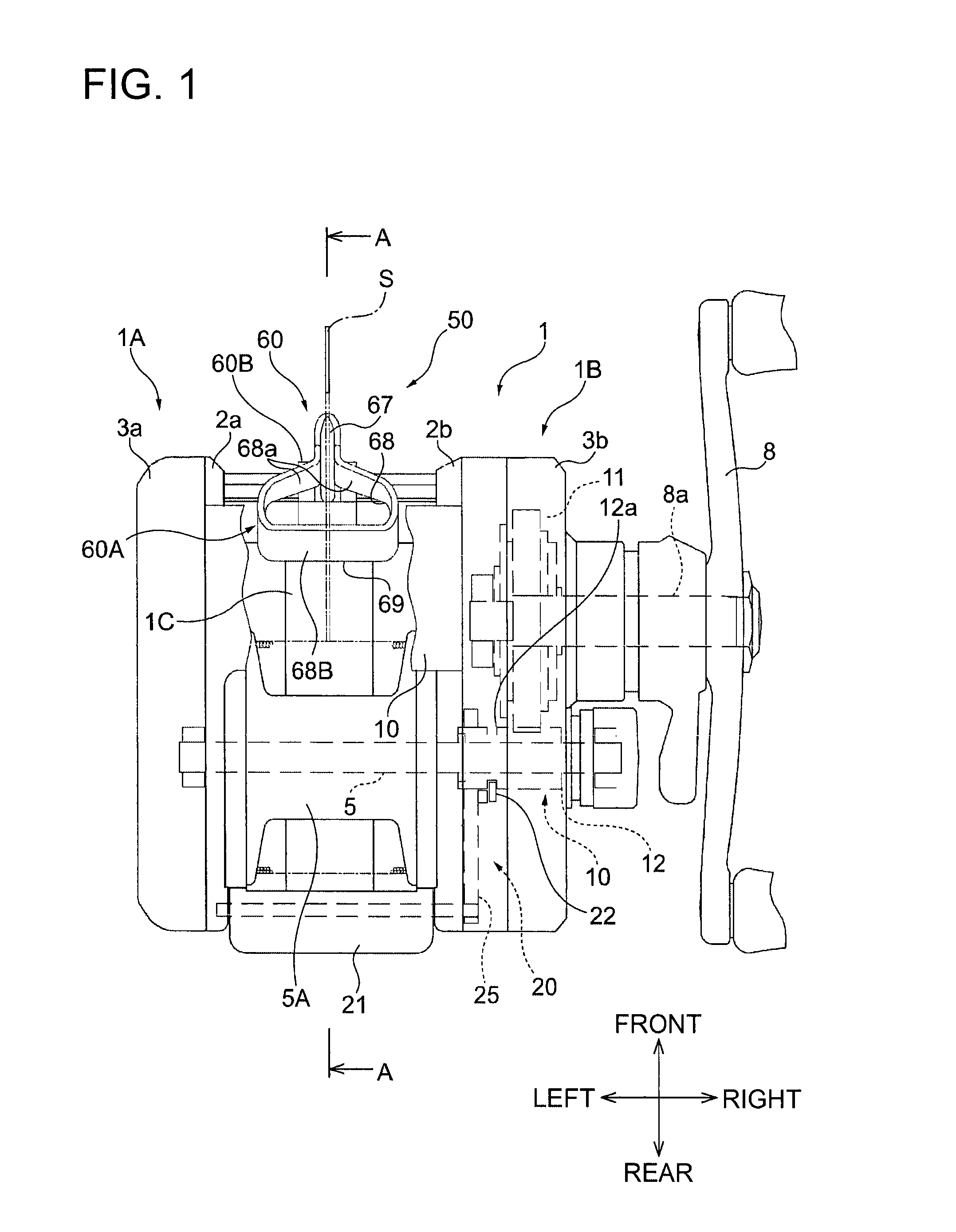
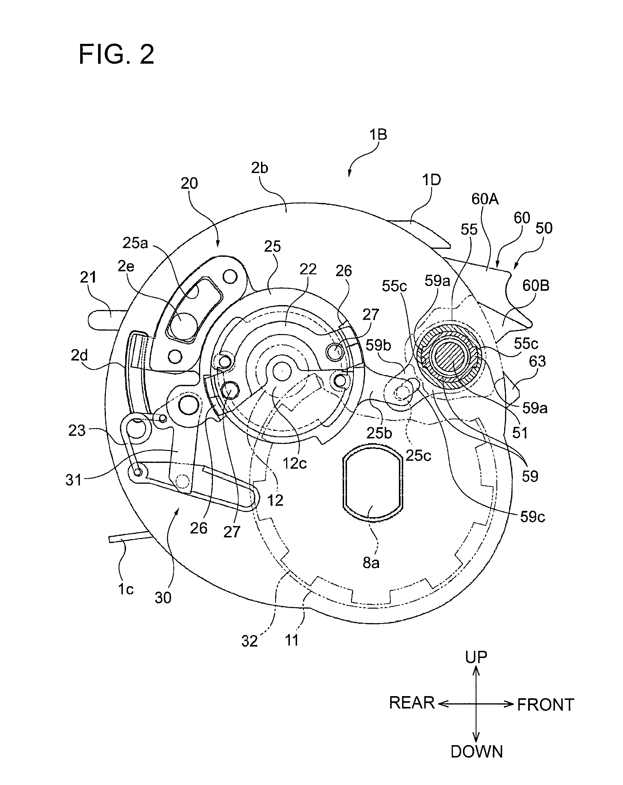
[0030]FIGS. 1 to 3 are diagrams illustrating a fishing reel according to the invention. FIG. 1 is a plan view in which a fishing line guide body is exposed, FIG. 2 is a side view illustrating the structure of a power transmitting portion of a clutch mechanism (clutch ON state), and FIG. 3 is another side view illustrating the structure of the power transmitting portion of the clutch mechanism (clutch OFF state). Meanwhile, in the following description, a front and rear direction, a left and right direction, and a vertical direction are defined as directions that are illustrated in FIGS. 1 and 2.

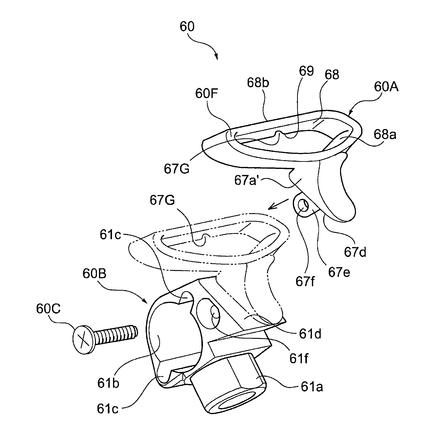
[0031]The fishing reel according to this embodiment includes a reel body 1 provided with left and right side plates 1A and 1B of which left and right frames 2a and 2b are covered with left and right covers 3a and 3b. A reel leg 1C, which is positioned between the left and right side plates and is mounted on a fishing rod (not illustrated), is formed integrally with the reel body. Further, a s...

second embodiment

[0072]Next, the invention will be described with reference to FIG. 13 to FIG. 16.

[0073]In regard to these drawings, FIG. 13 is a schematic side view illustrating a relationship between a clutch mechanism and a cover provided on a reel body, FIG. 14 is a side view illustrating a state in which a fishing line is threaded through a fishing line guide body in the fishing reel illustrated in FIG. 13 (clutch ON state), FIG. 15 is a front view of a level wind device of the fishing reel illustrated in FIG. 13 (clutch ON state), and FIG. 16 is a front view of the level wind device of the fishing reel illustrated in FIG. 13 (clutch OFF state). Meanwhile, members having the same functions as those of the first embodiment will be denoted by the same reference numerals and the detailed description thereof will be omitted.

[0074]In this embodiment, a cover member 80, which can be opened and closed in the vertical direction by being rotated about a rear side thereof serving as a rotation-base end p...


PUM


Abstract

A fishing reel includes a fishing line threading section (60A) through which a fishing line to be unreeled from a spool (5A) is threaded, a main body (60B) that is engaged with a worm shaft (51) provided between left and right side plates, a fishing line guide body (60) that reciprocates between the left and right side plates through the rotational drive of the worm shaft, and a clutch mechanism (20) that switches the spool (5A) between a fishing line winding state and a fishing line unwinding state. The fishing line guide body (60) is supported in front of the spool (5A) so as to be switched and movable between the fishing line unwinding state and the fishing line winding state, and the fishing line threading section (60A) and the main body (60B) are formed separately and integrated with each other.

Description

TECHNICAL FIELD[0001]The present invention relates to a fishing reel including a fishing line guide body that guides and winds a fishing line on a spool in parallel and is provided between side plates in front of the spool.BACKGROUND ART[0002]In the related art, a double-bearing fishing reel is provided with a level wind device so as to uniformly wind a fishing line on a spool that is rotatably supported between left and right side plates. The level wind device includes a worm shaft that is rotated in front of the spool in conjunction with a winding operation of a handle rotatably provided on one side plate, and a fishing line guide body that is engaged with the worm shaft and reciprocates in a left and right direction. Accordingly, when the fishing line is threaded through a fishing line threading section of the fishing line guide body, the fishing line can be wound on the spool in parallel.[0003]Incidentally, the above-mentioned fishing line guide body has a problem in that, for e...

Claims


Application Information

Patent Timeline
Patent Type & Authority Applications(United States)
IPC IPC(8): A01K89/015
CPCA01K89/015A01K89/01917A01K89/01918
Inventor UMEZAWA, YUUICHIKANO, SHUTA
Owner DAIWA SEIKO CORPORATION
Features
  • R&D
  • Intellectual Property
  • Life Sciences
  • Materials
  • Tech Scout
  • Unparalleled Data Quality
  • Higher Quality Content
  • 60% Fewer Hallucinations
Learn More