
Real-time dynamic non-planar projection apparatus and method

a non-planar projection, real-time technology, applied in the field of real-time dynamic non-planar projection apparatus and method, can solve the problems of insufficient technology for precisely correcting screen images, methods that cannot support projection onto a geometrical surface deformed in real time, and the range of color representation is inevitably reduced.

Inactive Publication Date: 2015-07-09
ELECTRONICS & TELECOMM RES INST
View PDF5 Cites 14 Cited by
  • Summary
  • Abstract
  • Description
  • Claims
  • Application Information

AI Technical Summary

Benefits of technology

The present invention aims to provide a non-planar projection apparatus and method that can reduce visual errors when projecting screen images onto a moving surface. The technical effect of this invention is to improve the accuracy and quality of projected images, making it easier for viewers to see and interpret the information being displayed.

Problems solved by technology

Further, there is technology for correcting a color error which is inevitably caused due to the pattern of a curtain having a color other than white while performing projection onto a curtain or the like which is a non-planar object, and then reducing distortion of images without the pattern of the curtain being exposed.
However, this technology is disadvantageous in that the range of color representation is inevitably reduced.
In the past, there have been various projection methods for an irregular screen, but such projection methods do not support projection onto a geometrical surface that is deformed in real time.
However, for such a case, technology for precisely correcting a screen image is insufficient.

Method used


Image

  • Real-time dynamic non-planar projection apparatus and method
  • Real-time dynamic non-planar projection apparatus and method
  • Real-time dynamic non-planar projection apparatus and method

Examples


Embodiment Construction

[0033]The present invention may be variously changed and may have various embodiments, and specific embodiments will be described in detail below with reference to the attached drawings.

[0034]However, it should be understood that those embodiments are not intended to limit the present invention to specific disclosure forms and they include all changes, equivalents or modifications included in the spirit and scope of the present invention.

[0035]The terms used in the present specification are merely used to describe specific embodiments and are not intended to limit the present invention. A singular expression includes a plural expression unless a description to the contrary is specifically pointed out in context. In the present specification, it should be understood that the terms such as “include” or “have” are merely intended to indicate that features, numbers, steps, operations, components, parts, or combinations thereof are present, and are not intended to exclude a possibility t...


PUM


Abstract

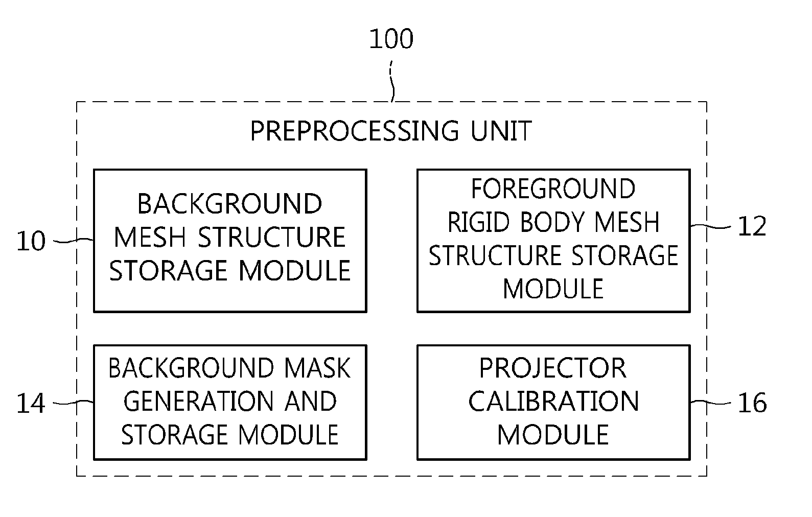
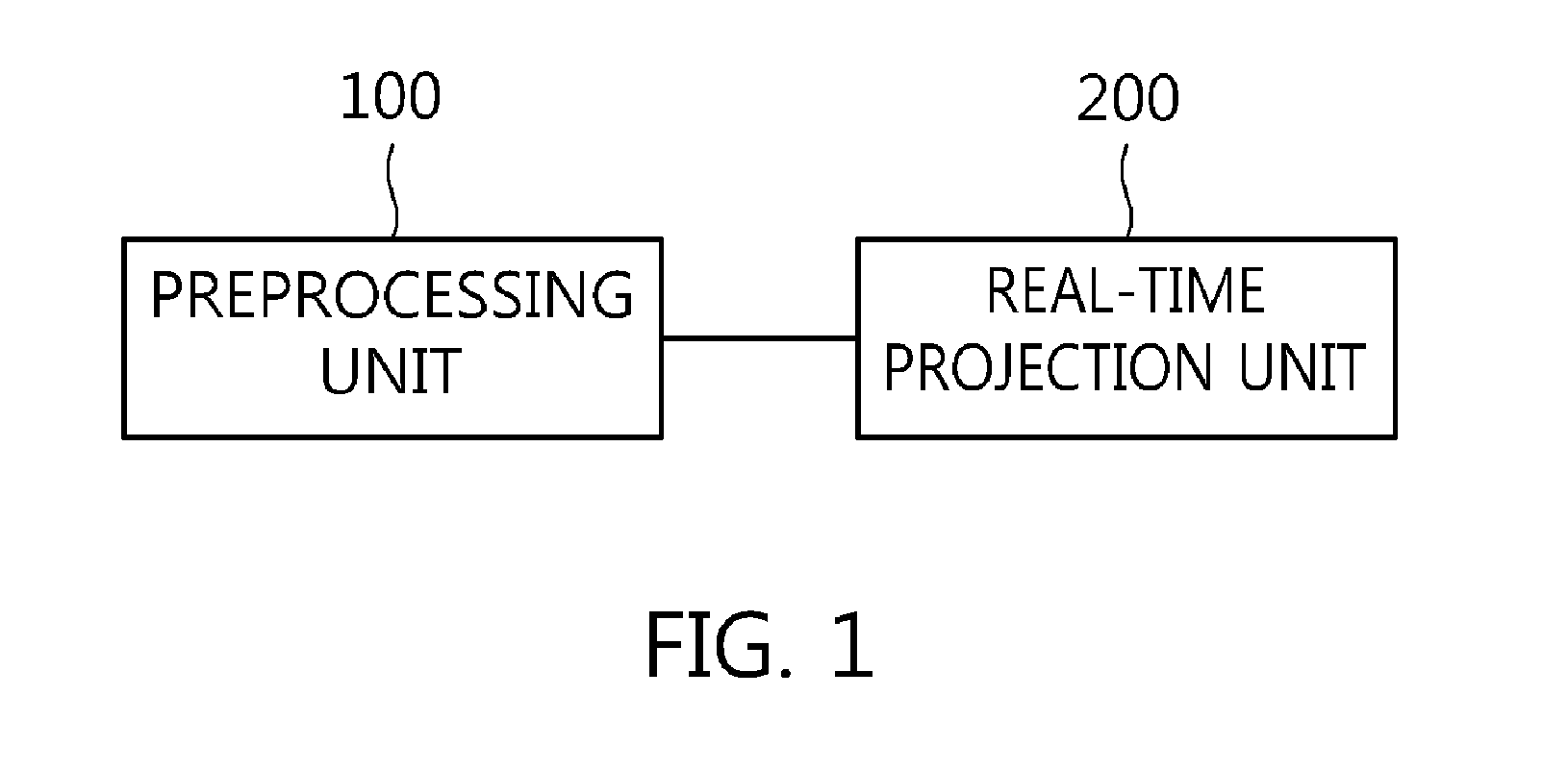
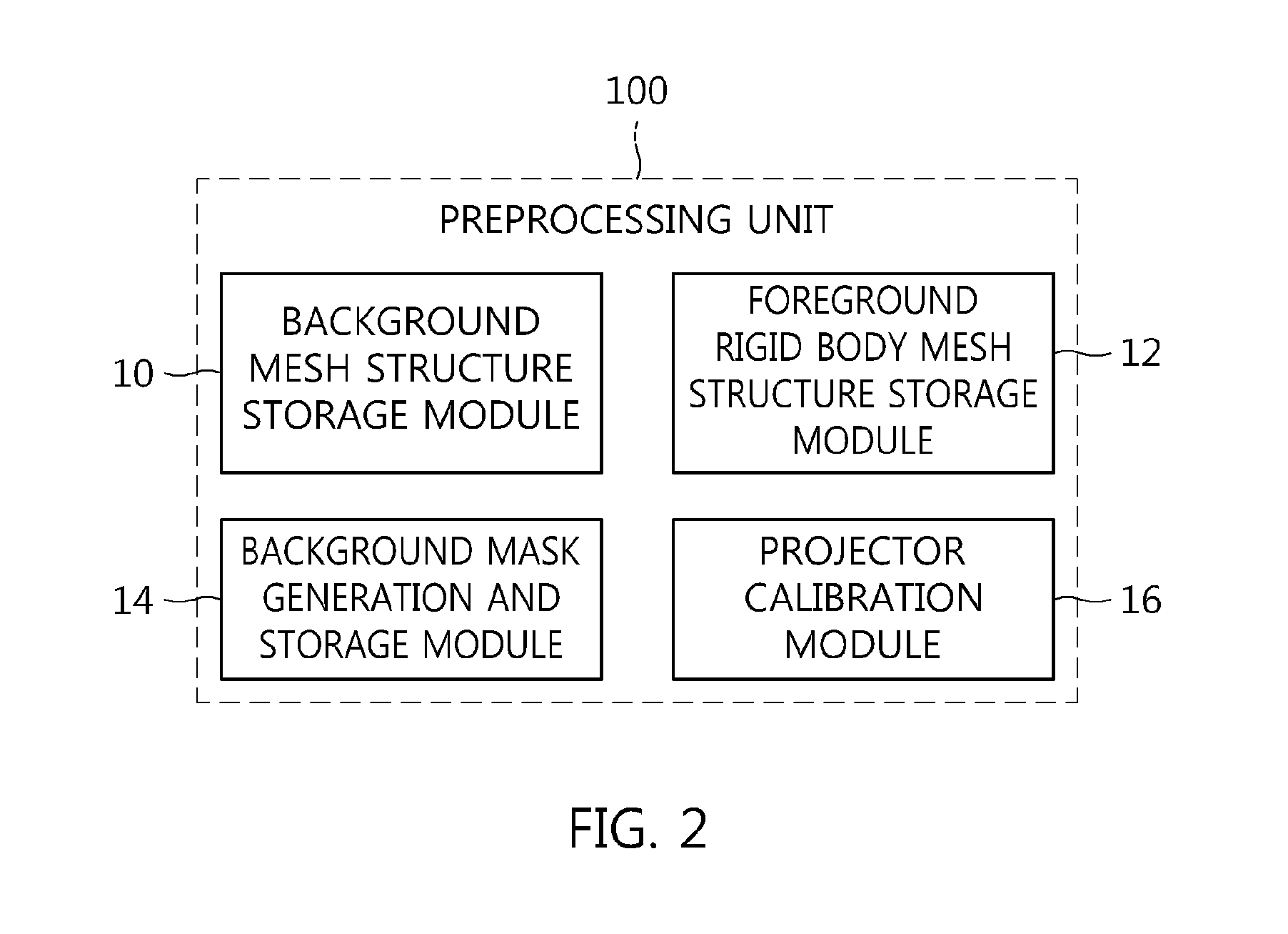
Disclosed herein is a real-time dynamic non-planar projection apparatus and method, which can reduce visual errors, such as distortion of a screen image or deviation from a border area, upon projecting screen images from a projector onto the surface of a non-planar object that is moved in real time. The presented real-time dynamic non-planar projection apparatus includes a preprocessing unit for preprocessing data related to a static part of a screen image to be projected onto a non-planar surface. A real-time projection unit classifies non-planar objects in the screen image to be projected onto the non-planar surface into a rigid body and a non-rigid body using data output from the preprocessing unit, respectively renders the rigid body and the non-rigid body depending on a viewer's current viewpoint, and projects rendered results onto the non-planar surface via projection mapping.

Description

CROSS REFERENCE TO RELATED APPLICATION[0001]This application claims the benefit of Korean Patent Application No. 10-2014-0001741, filed Jan. 7, 2014, which is hereby incorporated by reference in its entirety into this application.GROUND OF THE INVENTION[0002]1. Technical Field[0003]The present invention relates generally to a real-time dynamic non-planar projection apparatus and method and, more particularly, to a real-time dynamic non-planar projection apparatus and method, which divide non-planar objects that are moved or deformed in real time into rigid bodies and non-rigid bodies and then show a desired screen image using a beam projector.[0004]2. Description of the Related Art[0005]Various attempts have been made to shift the location and direction of a projector in real time for irregular objects (objects that can be easily mathematically calculated, such as a face, a sphere, a box, a cylinder, and a cone) and non-planar objects (objects, the faces of which are not planar and ...

Claims


Application Information

Patent Timeline
Patent Type & Authority Applications(United States)
IPC IPC(8): G06T15/20G06T17/20G06V10/24G06V10/26G06V20/00
CPCG06T17/20G06T15/205H04N9/3185H04N9/3182H04N9/3194G06T15/10G06V20/00G06V10/24G06V10/62G06V10/26G03B21/00G06T3/18
Inventor KIM, HANG-KEEKIM, YOUNG-HEEKIM, YONG-SUNKIM, KI-HONGCHO, HYUN-WOOKIM, JIN-HO
Owner ELECTRONICS & TELECOMM RES INST
Learn More