

Shock absorber
- Summary
- Abstract
- Description
- Claims
- Application Information
AI Technical Summary
Benefits of technology
Problems solved by technology
Method used
Image

Examples
first embodiment
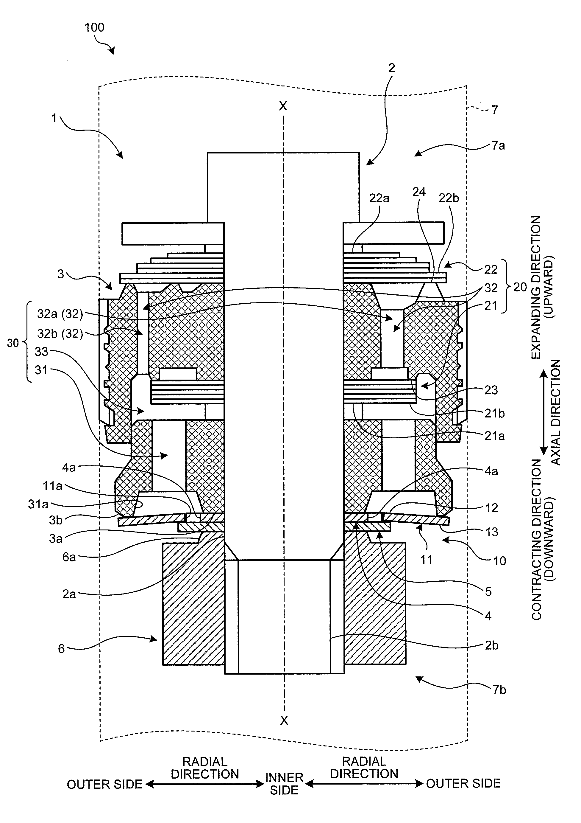
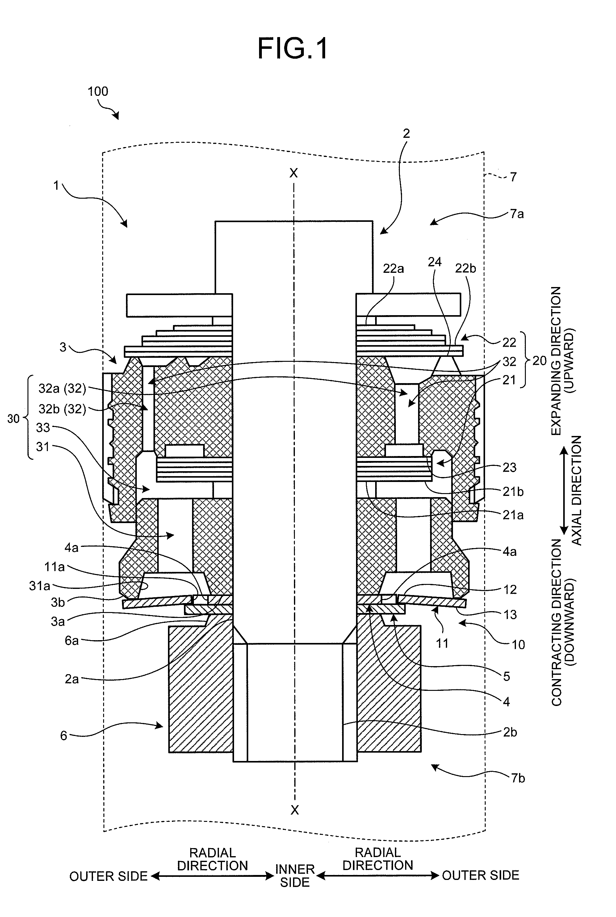
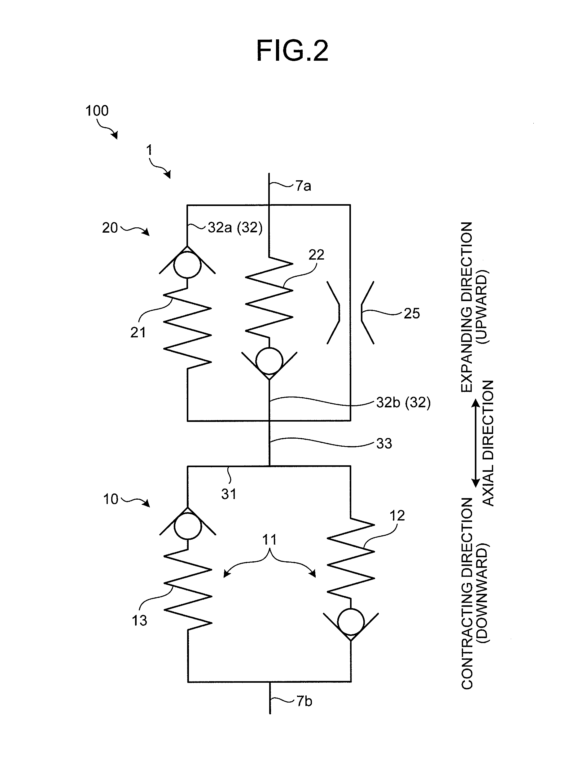
[0032]A first embodiment will be described with reference to FIG. 1 to FIG. 10. This embodiment relates to a shock absorber. FIG. 1 is a main part cross-sectional view of the shock absorber according to the first embodiment of the present invention. FIG. 2 is a diagram illustrating the function of the shock absorber according to the first embodiment. FIG. 3 is a perspective view illustrating the configuration members of the shock absorber according to the first embodiment. FIG. 4 is an enlarged view of a first valve of the shock absorber according to the first embodiment. FIG. 5 is a diagram illustrating the operation during contraction of the shock absorber according to the first embodiment. FIG. 6 is a diagram illustrating the operation during expansion of the shock absorber according to the first embodiment. FIG. 7 is a graph illustrating characteristics of the first valve and a second valve according to the first embodiment. FIG. 8 is a graph illustrating a characteristic of the...
second embodiment
[0091]A second embodiment will be described with reference to FIG. 12. In the second embodiment, the same reference sign will be given to the component having the same function as the first embodiment, and the repetitive description thereof will be omitted. FIG. 12 is a main part cross-sectional view of a shock absorber according to the second embodiment. FIG. 13 is a diagram illustrating the function of the shock absorber according to the second embodiment. A shock absorber 101 according to the second embodiment differs from the shock absorber 100 of the above-described first embodiment in that the first leaf valve 11 works only on the expansion side. In FIG. 12, the left side on the paper with respect to the center axis line X illustrates the state where the piston 1 moves in the expanding direction, and the right side on the paper with respect to the center axis line X illustrates the state where the piston 1 moves in the contracting direction.
[0092]As illustrated in FIG. 12, the...
third embodiment
[0097]A third embodiment will be described with reference to FIG. 14 to FIG. 17. In the third embodiment, the same reference sign will be given to the component having the same function as the first embodiment and the second embodiment, and the repetitive description thereof will be omitted. FIG. 14 is a main part cross-sectional view of a shock absorber according to the third embodiment. FIG. 15 is a perspective view illustrating the configuration members of the shock absorber according to the third embodiment. FIG. 16 is a diagram illustrating a substantive valve-closed state of the first leaf valve. FIG. 17 is a diagram illustrating a valve-opening state of the first leaf valve. A shock absorber 102 according to the third embodiment differs from the shock absorbers 100 and 101 in the above-described respective embodiments in that the first valve 10 generates different magnitudes of damping forces corresponding to the moving direction of the piston 1 with respect to the same magni...
PUM
 Abstract
Description
Claims
Application Information