Steering shock-absorbing device

A damping device and technology of damping force, applied in the direction of shock absorber, steering mechanism, spring/shock absorber, etc., to achieve the effect of restraining damping force and light handlebar manipulation

Inactive Publication Date: 2007-04-11
HONDA MOTOR CO LTD
View PDF6 Cites 0 Cited by
  • Summary
  • Abstract
  • Description
  • Claims
  • Application Information

AI Technical Summary

Problems solved by technology

[0004] However, including the above-mentioned conventional examples, there is no steering damper device that can be controlled according to the content of the handlebar manipulation. Therefore, it is desired to control the damping force in a manner that is appropriate according to the content of the handlebar manipulation.

Method used


Image

  • Steering shock-absorbing device
  • Steering shock-absorbing device
  • Steering shock-absorbing device

Examples


Embodiment Construction

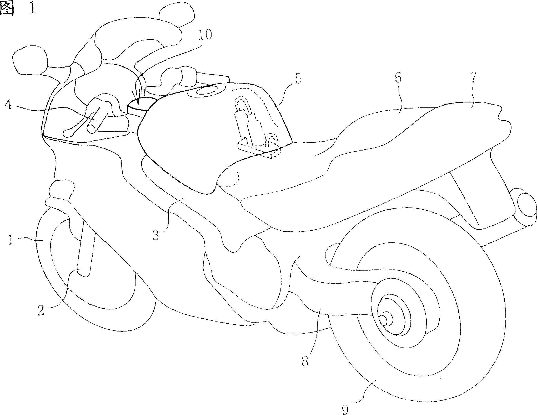
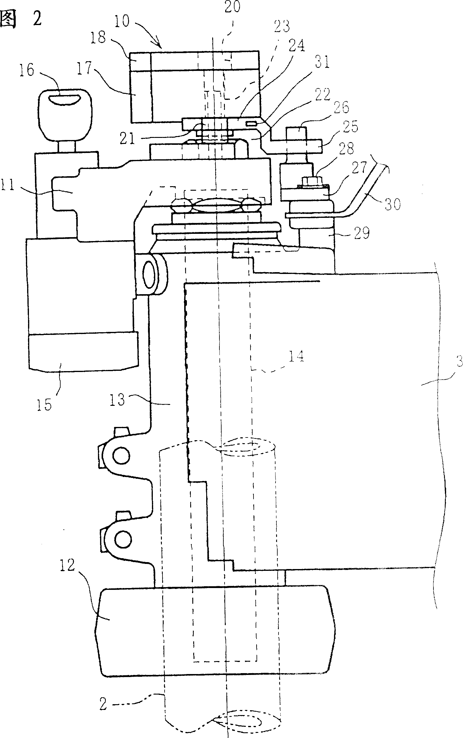
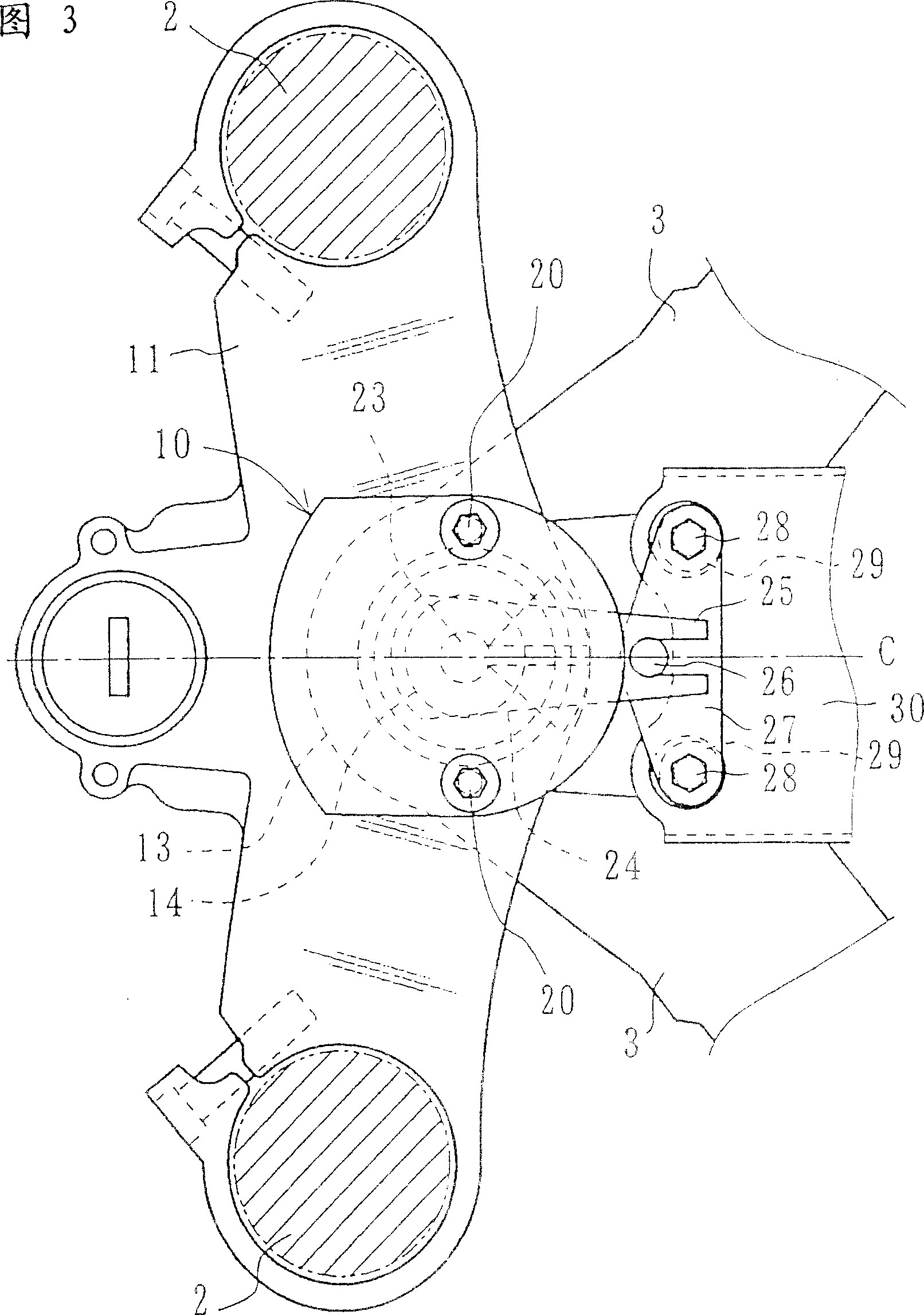
[0028] The first embodiment will be described below based on the drawings. Fig. 1 is a perspective view of a motorcycle to which the first embodiment is applied. Fig. 2 is a side view of the vehicle body front portion showing the steering damper device portion. Fig. 3 is a plan view of the portion shown in Fig. 2 . Fig. 4 is a view showing the main structure of the steering damper. Fig. 5 is a view showing the action.

[0029] In FIG. 1, the upper part of the front fork 2 supported at the lower end of the front wheel 1 is connected to the front part of the vehicle frame 3, which can be freely rotated with the handlebar 4. A fuel tank 5 is supported on the vehicle frame 3 . Symbol 6 is a seat, 7 is a rear cover, 8 is a rear rocker arm, and 9 is a rear wheel.

[0030] The steering damper is described below. As shown in FIGS. 2 and 3 , the steering damper 10 is provided between the upper connecting bridge 11 on which the handlebar 4 is mounted and the front end of the vehic...


PUM


Abstract

The invention generates a damping force in a steering damper only upon an unintentionally caused handle action when it is truly necessary to restrain the turning of the handle, according to whether the cause of a handle action is intentional or unintentional. In the invention, a rotation type steering damper (10) is provided coaxially with a steering shaft, and generation of a damping force or zero damping force is selected through changeover by a variable valve (38) provided in a bypass passage (37) for communication between a right liquid chamber (34) and a left liquid chamber (35) of the steering damper. The changeover is controlled by a control device (40), which functions based on the direction of a moment exerted on the steering shaft detected by a moment sensor (31) and the magnitude and direction of a rotational angular velocity concerning the turning of the steering shaft detected by a rotational angular velocity sensor (41), and so controls that a damping force is generated only when an unintentionally caused handle turning action opposite in direction to the moment is present and the rotational angular velocity has exceeded a predetermined threshold value.

Description

technical field [0001] The present invention relates to a steering damper for a motorcycle that attenuates handlebar vibration during running, and more particularly to a steering damper with variable damping force. Background technique [0002] In order to prevent handlebar vibration caused by reverse rotation etc. during disturbance, a steering damper device that generates a damping force to vibration is known (as an example, Japanese Patent No. 2593461 has been recorded). In addition, the damping force is variable so that the damping force is only generated when necessary, and the steering damping device that does not generate unnecessary damping force at other times is also known, for example, there are steering damping devices controlled according to the steering angle and driving speed (Japanese Unexamined No. 63-64888), steering damper etc. (Japanese Patent Fair No. 7-74023) controlled along with the variation of front wheel load. [0003] However, in the damping forc...

Claims


Application Information

Patent Timeline
Patent Type & Authority Patents(China)
IPC IPC(8): B62K21/08B62K21/00B62D5/06F16F9/12F16F9/46F16F9/50F16F15/02F16F15/023
CPCF16F9/125B60G2200/44B60G2300/12B62K21/08B60G2202/22B60G2400/44B60G2400/42F16F9/466B60G2600/184B62K21/00
Inventor 长谷川洋介板桥健康林宽二若林威文谷修
Owner HONDA MOTOR CO LTD
Why Eureka
Try Eureka