Electrical connector

Active Publication Date: 2015-07-16
LOTES
View PDF0 Cites 3 Cited by
  • Summary
  • Abstract
  • Description
  • Claims
  • Application Information

AI Technical Summary

Benefits of technology

The present invention improves the signal strength and reduces mutual electromagnetic interference between differential signal terminals by deflecting the connection ports and vertical portions inward and closer relative to the contact and welding portions, as well as widening the interval between the differential signal terminals from an oblique direction. The width of the grounding terminal and the vertical portions is also increased to reduce inductive coupling and electromagnetic interference between differential signal terminals.

Problems solved by technology

The conventional USB 2.0 has technical problems such as insufficient transmission speed and insufficient driving and operating power.
However, when this type of connector works, and in particular, when the connector works at a high frequency, mutual crosstalk inevitably occurs between a USB 2.0 terminal and a USB 3.0 terminal, thereby affecting signal transmission quality.
Although this stacked socket electrical connector conforms to the requirement of the portable electronic product on reduction of the space occupancy rate, the distance between various transmission terminals are also reduced while reducing the space occupancy rate, inevitably resulting in increasing of mutual electromagnetic crosstalk between signal terminals, thereby causing high-frequency instability and transmission signal distortion.
Therefore, a heretofore unaddressed need exists in the art to address the aforementioned deficiencies and inadequacies.

Method used


Image

  • Electrical connector
  • Electrical connector
  • Electrical connector

Examples


first embodiment

[0035]As shown in FIGS. 2, 3 and 5, in a first embodiment, an electrical connector of the present invention includes an insulating body, and a first terminal group 4 and a second terminal group 5 accommodated in the insulating body.

[0036]As shown in FIG. 3, the insulating body includes a base 320, a first tongue 321 extending forward from the base 320, a seat 322 located below the first tongue 321 and the base 320, a second tongue 323 extending forward from the seat 322, and a spacer 324 located behind the base 320. A lower side of a front end of the first tongue 321 is provided with multiple first receiving slots (not shown). The seat 322 is provided with multiple second receiving slots (not shown). A lower side of the second tongue 323 is provided with multiple third receiving slots (not shown). The spacer 324 has a row of fourth receiving slots (not shown), and a row of fifth receiving slots (not shown) located behind the fourth receiving slots (not shown).

[0037]As shown in FIGS....

second embodiment

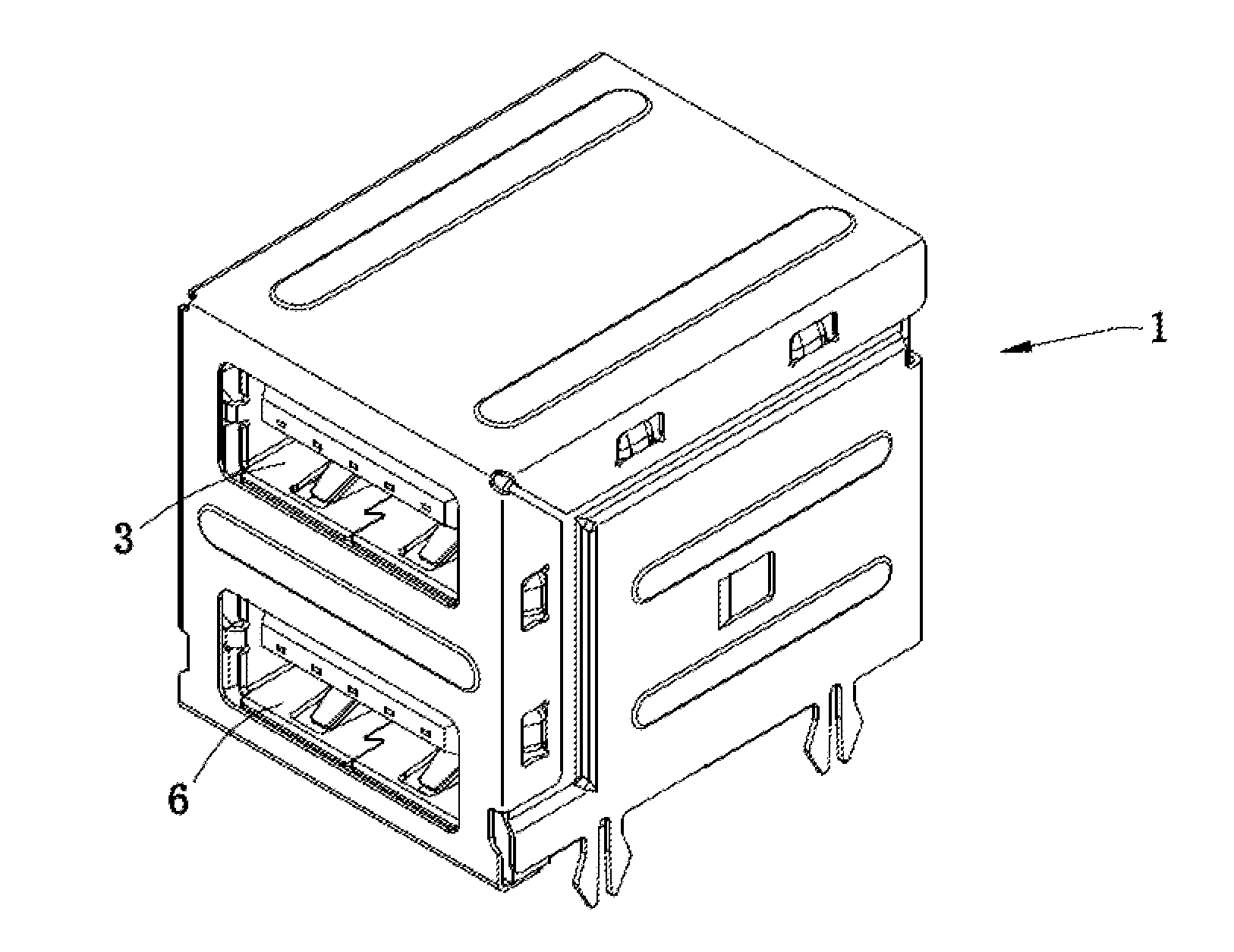
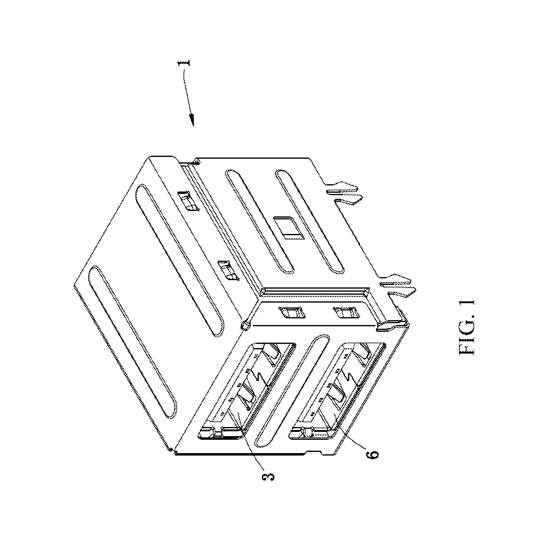
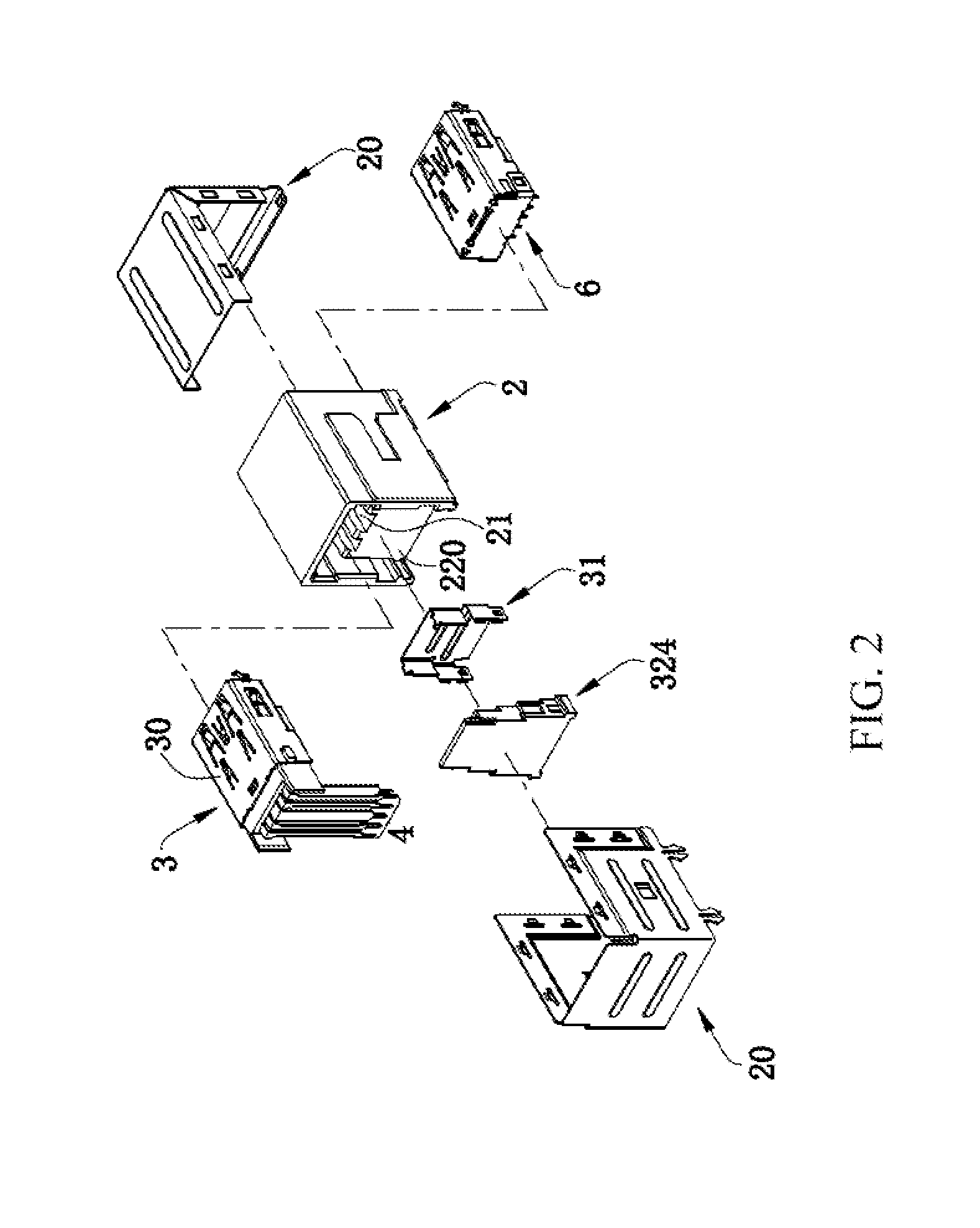
[0043]As shown in FIGS. 1 to 6, in a second embodiment, the electrical connector of the present invention is a stacked electrical connector 1 for electrically connecting to a circuit board, and providing connections for two electronic products using the USB transmission standard at the same time. The stacked electrical connector includes an insulating housing 2, a first connector 3, and a second connector 6.

[0044]As shown in FIG. 2 and FIG. 7, the insulating housing 2 is internally provided with a first accommodating cavity 21 through the insulating housing 2 from front to back, a second accommodating cavity 22 is located below the first accommodating cavity 21, the back end of the second accommodating cavity 22 is provided with a vertical retaining wall 220, and a metal housing 20 covers the insulating housing 2.

[0045]As shown in FIG. 2 and FIG. 7, the first connector 3 is the same as the electrical connector in the first embodiment, and is assembled into the first accommodating ca...


PUM


Abstract

An electrical connector includes an insulating body, and a first and second terminal groups located in the insulating body. The second terminal group is located below the first terminal group. The first terminal group has a first grounding terminal, and two pairs of first differential signal terminals located at two sides. The second terminal group has a pair of second differential signal terminals, a second grounding terminal and a power supply terminal located at two sides. The first differential signal terminal, the first and second grounding terminals, and the power supply terminal have a first, third, fourth and fifth fixing portions fixed to the insulating body, and a first, third, fourth and fifth vertical portions bends downward and extends from the corresponding fixing portions. The first grounding terminal is wider than the second differential signal terminal. The fourth and fifth vertical portions are wider than the first vertical portion.

Description

CROSS-REFERENCE TO RELATED APPLICATION[0001]This non-provisional application claims priority under 35 U.S.C. §119(a) on Patent Application No. 201420013046.2 filed in P.R. China on Jan. 10, 2014, the entire contents of which are hereby incorporated by reference.[0002]Some references, if any, which may include patents, patent applications and various publications, may be cited and discussed in the description of this invention. The citation and / or discussion of such references, if any, is provided merely to clarify the description of the present invention and is not an admission that any such reference is “prior art” to the invention described herein. All references listed, cited and / or discussed in this specification are incorporated herein by reference in their entireties and to the same extent as if each reference was individually incorporated by reference.FIELD OF THE INVENTION[0003]The present invention relates to an electrical connector, and particularly to an electrical connec...

Claims


Application Information

Patent Timeline
IPC IPC(8): H01R27/02H01R24/64H01R13/6463
CPCH01R27/02H01R24/64H01R13/6463H01R12/724H01R13/6471H01R25/006
Inventor YAO, GUI LIN
Owner LOTES
Why Eureka
Try Eureka