Wall plate assembly

Inactive Publication Date: 2009-04-23
SURE FIRE ELECTRONICSAL CORP
View PDF13 Cites 2 Cited by
  • Summary
  • Abstract
  • Description
  • Claims
  • Application Information

AI Technical Summary

Benefits of technology

[0011]According to another aspect of the present invention, the signal amplifier comprises a connection interface, which is used for receiving a HDMI (High-Definition Multimedia Interface) connector of a HDMI (High-Definition Multimedia Interface) cable, a circuit board for enhancing the signal strength of the signal transmitting through the HDMI connector that is connected to the connection interface, and an adapter interface for output of the signal strength-enhanced signal.

Problems solved by technology

Arranging electric cables and connection devices on the outside of the ceiling, wall or floor destructs the sense of beauty of the house.
Further, it is not safe to have electric cables and connection devices been exposed to the outside.
However, if a high frequency transmission line is connected to multiple users through a router and the receiver is spaced from the transmitter at a long distance, the strength of the signal being transmitted through the transmission line will be attenuated, causing video signal distorsion or interruption.
Therefore, the application of a high frequency transmission line is limited.
1. If the location of the signal amplifier is far from the power source and the signal amplifer cannot obtain an external power supply, the signal amplifer may be unable to function well due to power low.
2. If the location of the signal amplifier is far from the signal transmitting side or signal receiving side, the effective length of the transmission line is limited, and the problem signal attenuation, signal interruption or signal instability may occur.
3. During signal transmission, the signal amplifier, the signal amplifer gives no indication. In case of signal instability during transmission due to a failure of the signal amplifier, the user or mechanic cannot quickly find out the problem, and much time will be wasted before the problem of the signal amplifier is checked.

Method used


Image

  • Wall plate assembly
  • Wall plate assembly
  • Wall plate assembly

Examples


Embodiment Construction

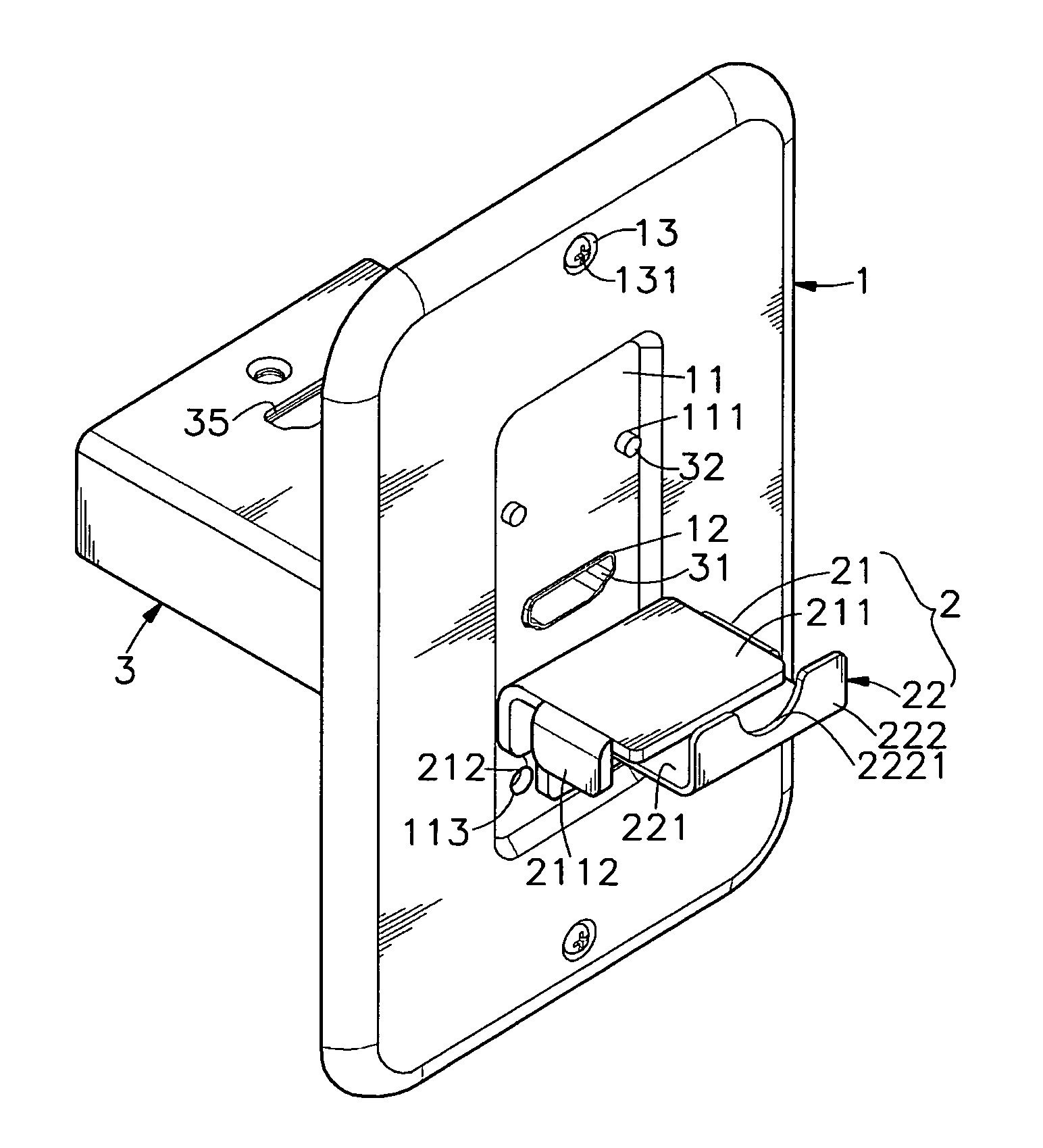
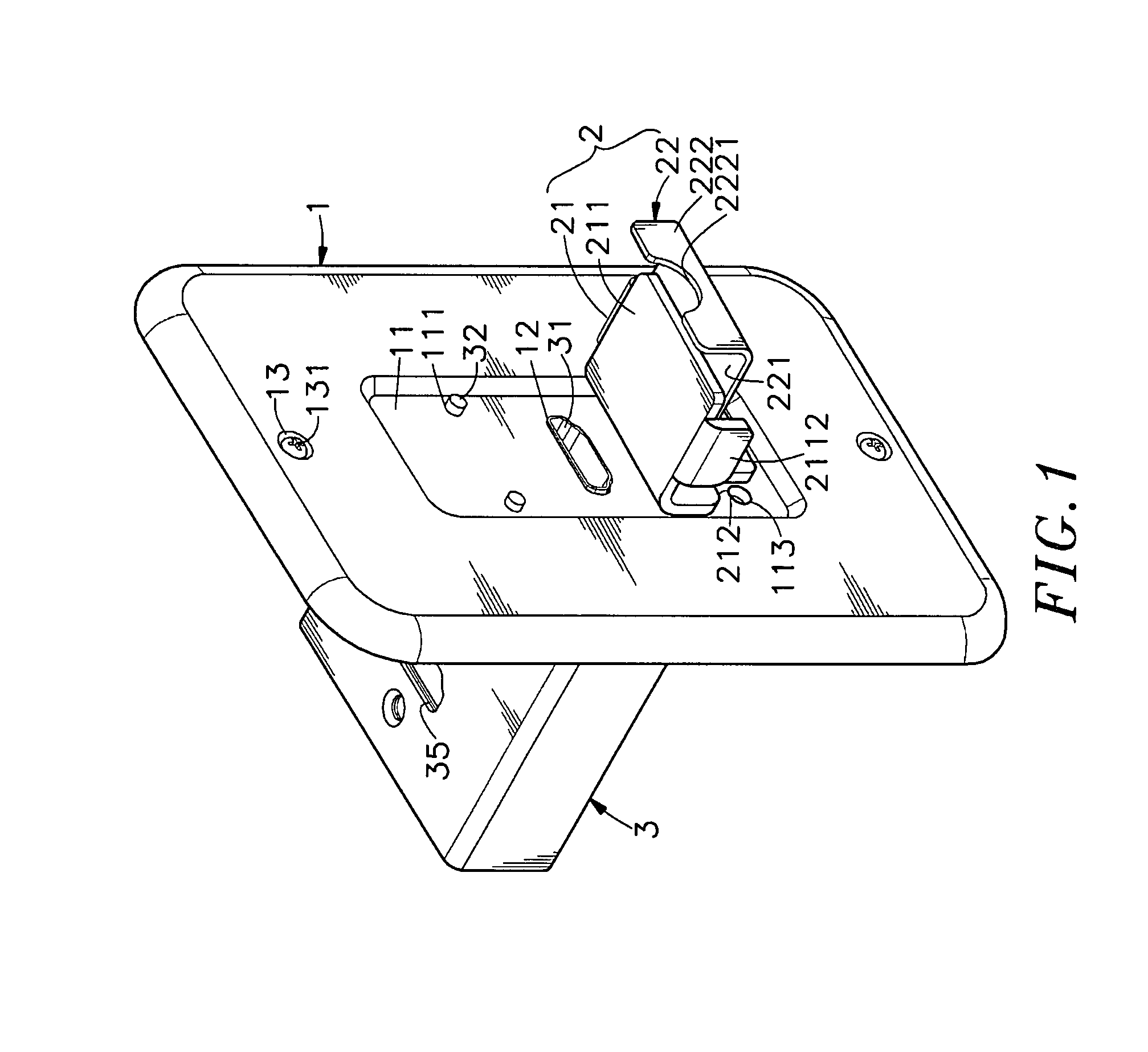
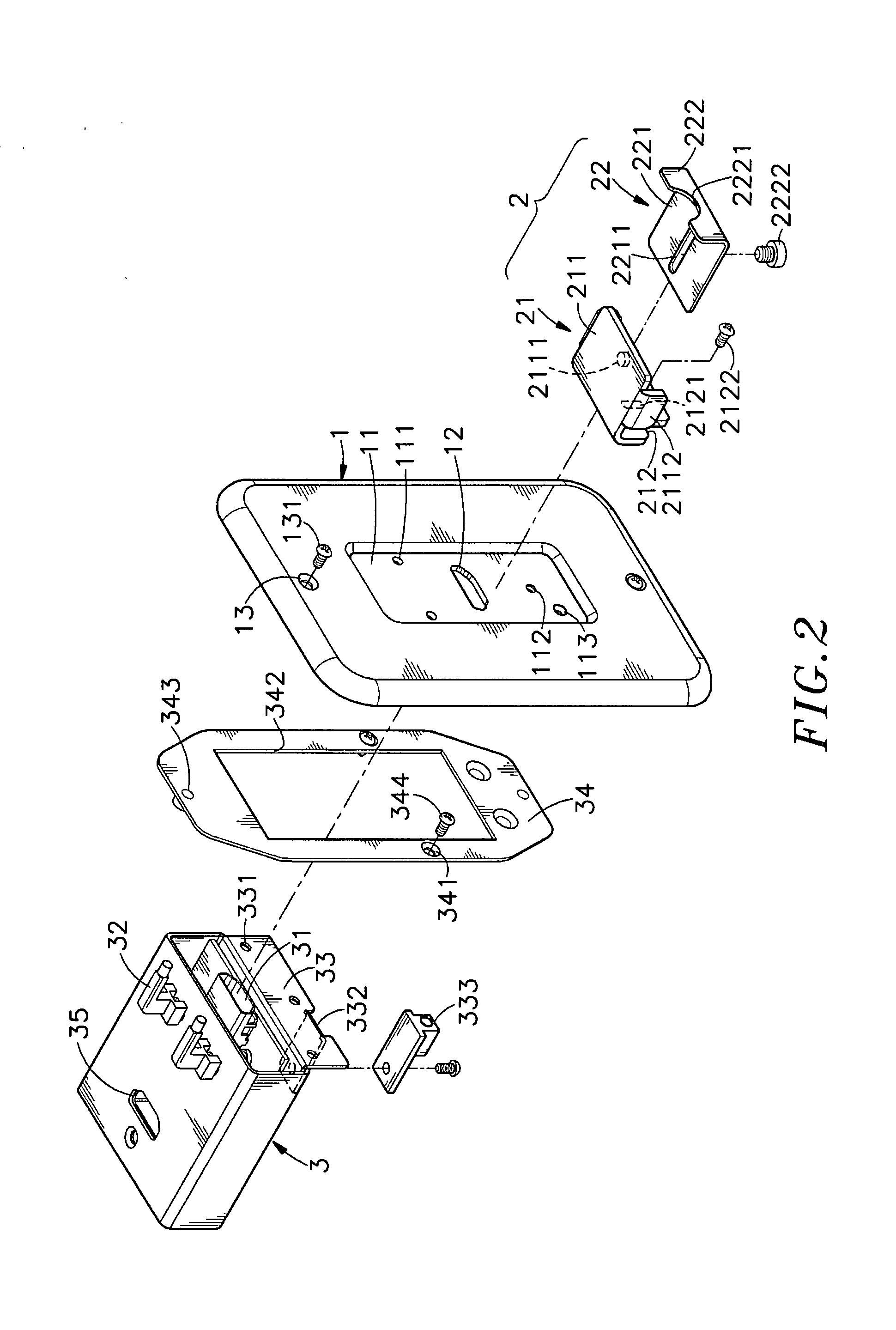
[0022]Referring to FIGS. 1˜3, a wall plate assembly for electric connector in accordance with the present invention is shown comprised of a wall plate 1, a support device 2, a signal amplifier 3 and a power connector 333.

[0023]The wall plate 1 has a front recess 11 on it front side, an insertion slot 12 cut through the front recess 11 on the middle, a plurality of through holes 111, a screw hole 112 and a power plug hole 113 cut through the front recess 11 at selected locations, and a plurality of mounting holes 13 cut through the front and back sides beyond the front recess 11 and respectively provided with a respective fastening member, for example, screw 131 for fastening to the wall.

[0024]The support device 2 is comprised of a first support frame 21 and a second support frame 22. The first support frame 21 and the second support frame 22 are movable relative to each other. The first support frame 21 has a horizontal panel 211 and a vertical panel 212 connected at right angles. T...


PUM


Abstract

A wall plate assembly includes a wall plate with an insertion slot for the installation of a HDMI (High-Definition Multimedia Interface) connector of a HDMI cable and a power plug hole for the insertion of a power plug, a signal amplifier connected to the back side of the wall plate for receiving the installed HDMI connector and amplifying the signal, a support device, which comprises a first support frame vertically adjustably fastened to the wall plate below the insertion slot and a second support frame horizontally adjustably fastened to the first support frame for holding down the installed HDMI connector on the first support frame, and a power connector aimed at the power plug hole for receiving a power plug to provide the signal amplifier with the necessary working voltage.

Description

BACKGROUND OF THE INVENTION[0001]1. Field of the Invention[0002]The present invention relates to a wall plate structure for receiving a HDMI (High-Definition Multimedia Interface) connector and more particularly, to a wall plate assembly that has a support device adjustable to hold down the installed HDMI connector, a signal amplifier to enhance signal strength, and a power connector for receiving a power plug to provide with signal amplifier with the necessary working voltage.[0003]2. Description of the Related Art[0004]Following fast development of high technology, advanced and sophisticated consumer electronic products are continuously created and put into market. In a house, many electric cables and connection devices may be arranged on the ceiling, wall or floor for the installation of electronic products. Arranging electric cables and connection devices on the outside of the ceiling, wall or floor destructs the sense of beauty of the house. Further, it is not safe to have elec...

Claims


Application Information

Patent Timeline
IPC IPC(8): H05K7/00
CPCH05K7/00H01R13/73H01R24/76H02G3/14H02G3/18
Inventor WANG, CHANG-PIN
Owner SURE FIRE ELECTRONICSAL CORP
Why Eureka
Try Eureka