Stitchless dorsal padding for protective sports gloves and other protective gear

a technology for sports gloves and dorsal padding, applied in racket sports, protective clothing, kitchen equipment, etc., can solve problems such as loose fit, achieve the effects of reducing the risk of injury, increasing flexibility, and ensuring the user's hand and fingers are protected

Active Publication Date: 2015-07-23
ABDELMALEK ANTHONY
View PDF10 Cites 24 Cited by
  • Summary
  • Abstract
  • Description
  • Claims
  • Application Information

AI Technical Summary

Benefits of technology

[0012]In one aspect, a protective glove includes a hand receiving portion that includes a plurality of finger portions, a thumb portion, a metacarpal portion and a wrist portion. The hand receiving portion includes a dorsal side and a palmar side. The dorsal side of the hand receiving portion comprises a unitary dorsal panel formed from an inner scrim material and a plurality of protective elements molded directly to an exterior surface of the inner scrim. The plurality of protective elements are formed in an array of discrete islands each separated by zero-elevation interstitial spaces. This array provides increased protection to the user's fingers, hands, wrists, and lower forearms while maintaining utmost flexibility and tactile feel on both palmar and dorsal sides of the glove, increasing flexibility where needed without compromising protection. Flexibility is desired by the wearer so as to impart freedom of movement to the fingers, hand, wrists and lower forearms needed to maintain an accurate tactile feel for the lacrosse, hockey or other sports stick during a match, while protection is required to reduce injury.
[0013]The unitary dorsal panel is sewn circumferentially to the palmer sections of the glove, with or without gussets and / or gusset stitching (for example, gussets are typically sewn between the dorsal and palmar sides of gloves running alongside the fingers). The cut pattern for the palmar section may vary but an embodiment is shown that includes three discrete sections: a finger-receiving section; a palm section, and a thumb section. In accordance with the invention, the palmar section is sewn end-to-end across the dorsal panel, with or without gussets, and the glove is inverted. The finger-receiving section and thumb section are then sewn on and the glove turned outside-in yielding internal seams (“inside stitching”). For this inside stitching the present invention provides an additional advantage. The typical reversing out of gloves dictates a minimum gusset width, which results in a looser fit. The invention facilitates a tighter standard for gusset width, which translates into a tighter fit. Of course, the finger-receiving section and thumb section may alternatively be sewn together exteriorly without inversion (“outside stitching”).

Problems solved by technology

The typical reversing out of gloves dictates a minimum gusset width, which results in a looser fit.

Method used


Image

  • Stitchless dorsal padding for protective sports gloves and other protective gear
  • Stitchless dorsal padding for protective sports gloves and other protective gear
  • Stitchless dorsal padding for protective sports gloves and other protective gear

Examples


example 1

Sonic-Welded Dorsal Panel

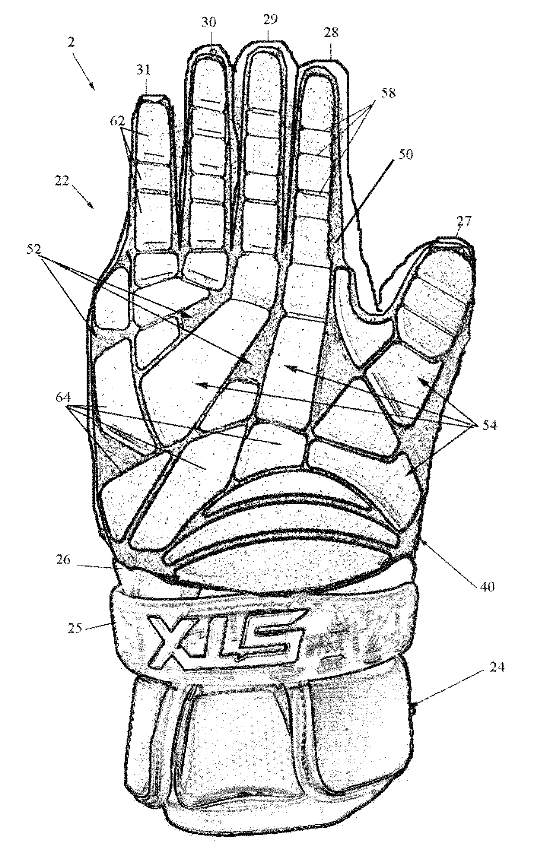
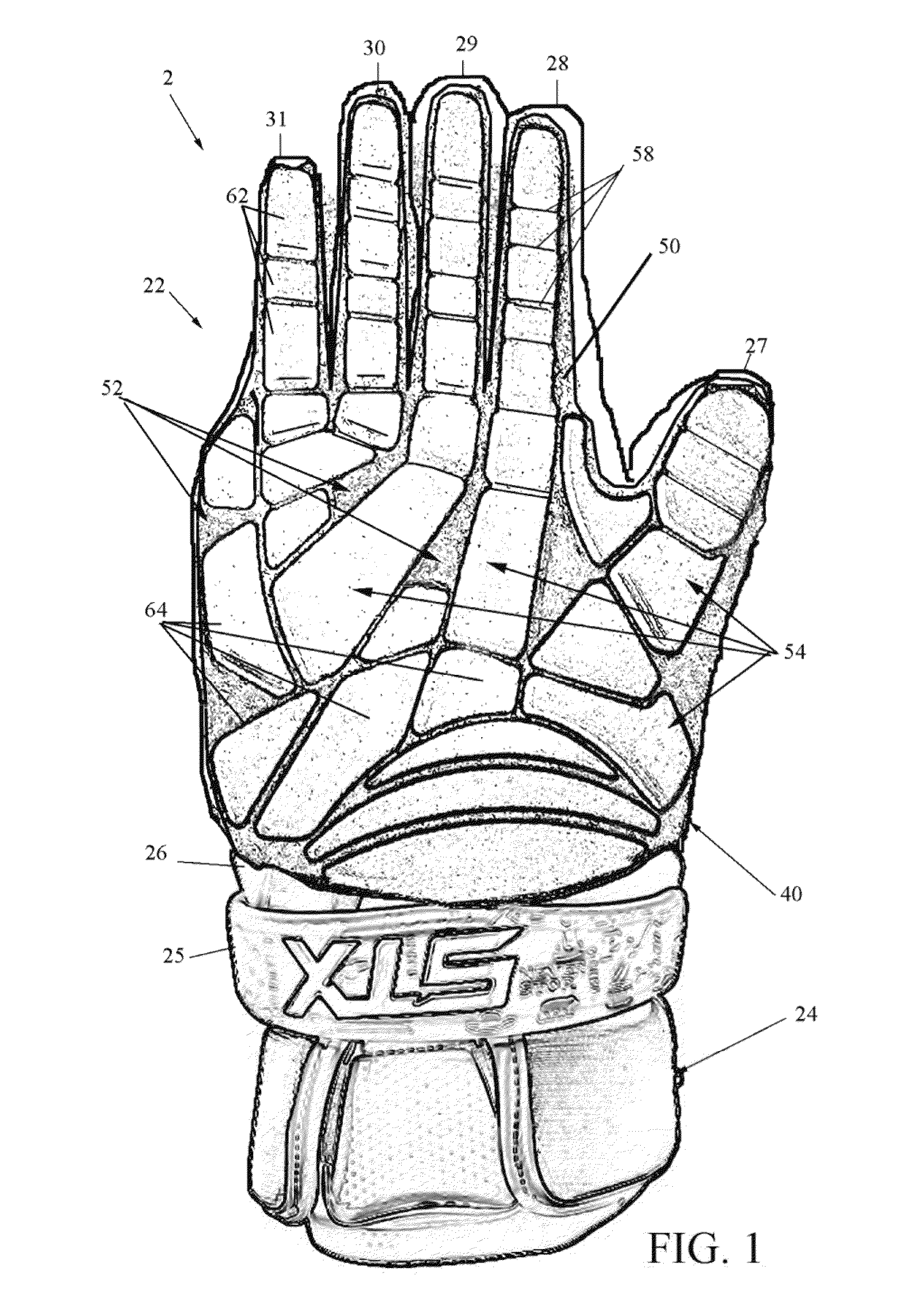
[0052]FIG. 5 is a process drawing illustrating the process for making a dorsal section of glove 2 for the embodiment of FIG. 1. Initially, at Step 1 the entire array of protective pads 52 is produced by either cold or heat compression in a tool, for example, cast-in-place by pour-casting into a two-part mold. At step 2, the protective pads 52 can be die-cut either post compression or during compression to attain their finished form. As seen at Step 3 the protective elements are placed back into the tool / mold and pressed onto a substrate using an adhesive film laid overtop pads 52 to keep them registered. As seen at Step 4, the combined film, substrate and protective pads 52 are placed into a flatbed high frequency welding station 100 as seen at B. To perform HF welding, two opposing die platens 150, 160 act as capacitor plates. An oscillating electrical current is applied to the mold 72 / fabric blank 62 combination between the die platens 150, 160. The oscill...

example 2

Textile Reinforced Compression Molded Foam Rubber Dorsal Panel

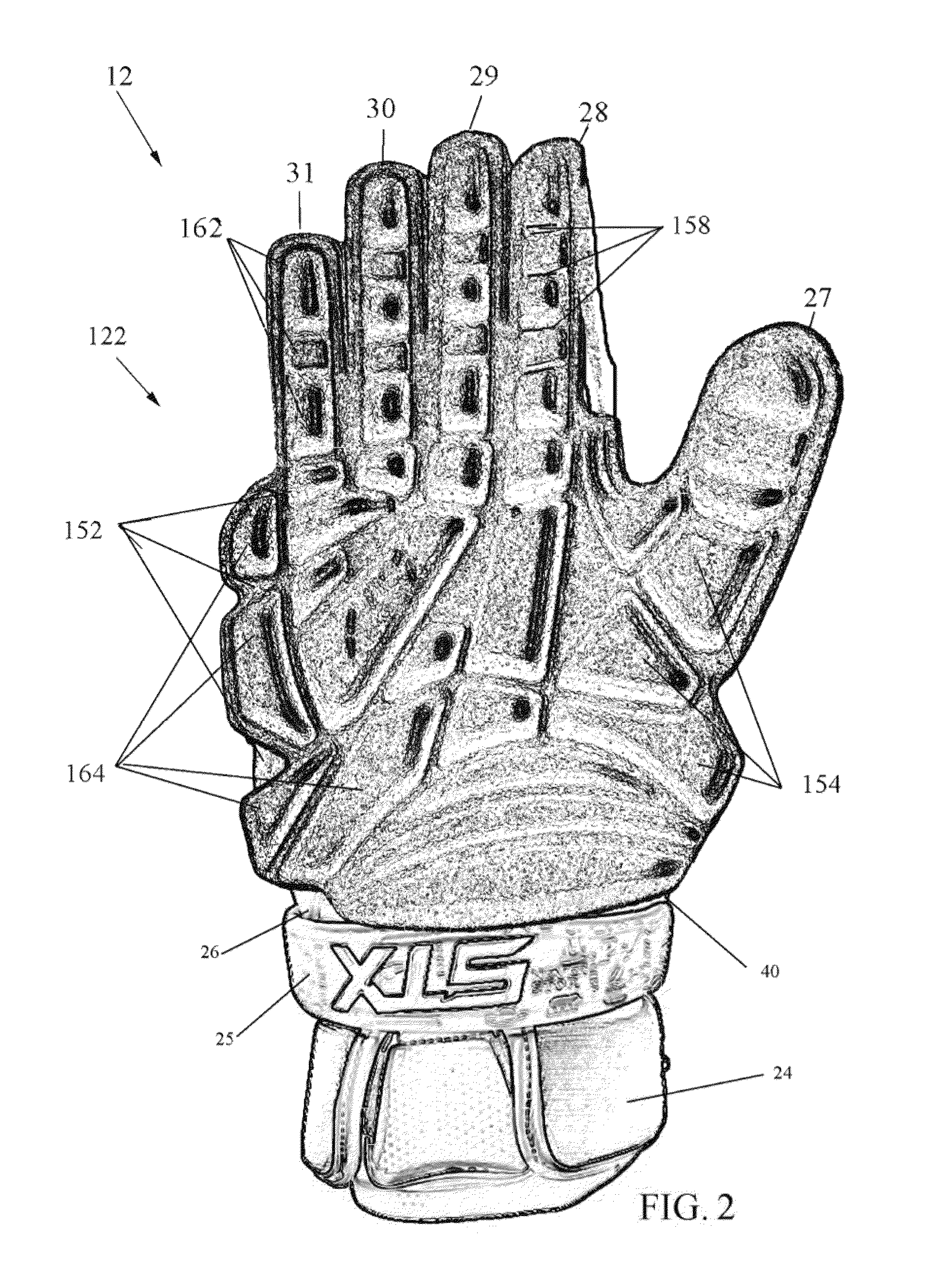
[0054]FIG. 6 is a process drawing illustrating the process for making a dorsal section of glove 2 for the embodiment of FIG. 2. Initially, at Step 1a mold fabricated with protective element cavities is pre-heated.

[0055]At Step 2 an optional thermoplastic polyurethane (TPU) film is laid on the bottom portion of the mold. One skilled in the art should understand that the TPU film may be omitted to reduce manufacturing cost.

[0056]At Step 3 the mold is closed and dorsal section of glove 2 is vacuum formed by releasing the air out of the bottom portion of the tool / mold so that the TPU film lines the bottom of the tool. At step 4 polyurethane is poured into the tool / mold using multiple gates, to allow the polyurethane to completely fill the tool cavities.

[0057]At Step 5 the tool is put on a conveyer through an oven. The polyurethane thermally expands and fills the tool / mold cavities. At Step 6 the tool is opened. At Step 7 a su...


PUM


Abstract

A protective glove having a unitary dorsal panel formed from an inner scrim material and a plurality of protective elements molded directly to an exterior surface of the inner scrim. The plurality of protective elements are formed in an array of discrete islands each separated by zero-elevation interstitial spaces. The unitary dorsal panel is sewn or otherwise attached circumferentially to the palmer sections of the glove. This array provides increased protection to the user's fingers, hands, wrists, and lower forearms while maintaining flexibility and tactile feel on both palmar and dorsal sides of the glove, increasing flexibility where needed without compromising protection.

Description

CROSS-REFERENCE TO RELATED APPLICATION(S)[0001]The present application derives priority from U.S. provisional patent application No. 61 / 930,311 filed Jan. 22, 2014.BACKGROUND OF THE INVENTION[0002]1. Field of the Invention[0003]The present invention relates generally to padding for lacrosse gloves and other athletic apparel and accessories, and more particularly, to a protective sports glove and stitch less dorsal padding for the same that provides improved flexibility, increased protection, finer tactile feel and economy of manufacture.[0004]2. Description of the Background[0005]Protective sports gloves are commonly used and, indeed, are required to be used in many organized sports such as lacrosse, hockey, and other contact sports. Such gloves protect the wearer from impact of lacrosse sticks, hockey sticks, balls, pucks, skates, and other players.[0006]Protective sports gloves include padding to protect the player's fingers, hands, wrists and lower forearms. Despite their protect...

Claims


Application Information

Patent Timeline
Patent Type & Authority Applications(United States)
IPC IPC(8): A63B71/14A41D19/015
CPCA41D19/01523A63B71/141A41D13/0156A41D2600/10A63B2102/14A63B2102/24
Inventor ABDELMALEK, ANTHONY
Owner ABDELMALEK ANTHONY
Why Eureka
Try Eureka