Fuel injection system of an internal combustion engine

a fuel injection system and internal combustion engine technology, applied in the direction of fuel injection apparatus, charge feed system, combustion engine, etc., can solve the problems of reducing undesirable wetting of the walls of the combustion chamber, and achieve the effect of reducing undesirable wetting of the walls and increasing pollutant emissions

Active Publication Date: 2015-07-23
DAIMLER AG
View PDF3 Cites 2 Cited by
  • Summary
  • Abstract
  • Description
  • Claims
  • Application Information

AI Technical Summary

Benefits of technology

[0009]In a fuel injection system of an internal combustion engine, having a combustion chamber with at least one intake valve at an intake side and with at least one exhaust valve at an exhaust side of the combustion chamber and a central injection nozzle for injecting fuel into the combustion chamber, the injection nozzle has injection orifices which are designed and oriented in such a way that a first quantity of fuel is injected into the intake side, a second quantity of fuel injected is into the exhaust side, and a third quantity of fuel which is about equal to the first quantity and greater than the second quantity is injected into a boundary area between the intake and the exhaust sides, providing for a low-emission operation of the internal combustion engine.
[0010]The intake side and exhaust side are defined essentially via the respective position of the intake and exhaust valves. Since, due to an air mass flow in the direction of the exhaust side which is intensified in the vicinity of the injection nozzle, fuel injected into this area may undesirably reach the wall of the combustion chamber particularly quickly, and at that location may bring about the above-mentioned undesirable effects, the reduction according to the invention of the quantity of fuel injected into the exhaust side results in decreased undesirable wetting of the walls of the combustion chamber. In the ideal case, such undesirable wetting with fuel may even be completely avoided. In particular, increased pollutant emissions may be avoided in this way.
[0011]The at least one injection orifice for the intake side preferably has a first opening diameter which is larger than a second opening diameter of the at least one injection orifice for the exhaust side. The reduction according to the invention of the quantity of injected fuel in the area of the exhaust side compared to the intake side may thus be achieved in a technically simple manner.

Problems solved by technology

Since, due to an air mass flow in the direction of the exhaust side which is intensified in the vicinity of the injection nozzle, fuel injected into this area may undesirably reach the wall of the combustion chamber particularly quickly, and at that location may bring about the above-mentioned undesirable effects, the reduction according to the invention of the quantity of fuel injected into the exhaust side results in decreased undesirable wetting of the walls of the combustion chamber.

Method used


Image

  • Fuel injection system of an internal combustion engine
  • Fuel injection system of an internal combustion engine

Examples


Embodiment Construction

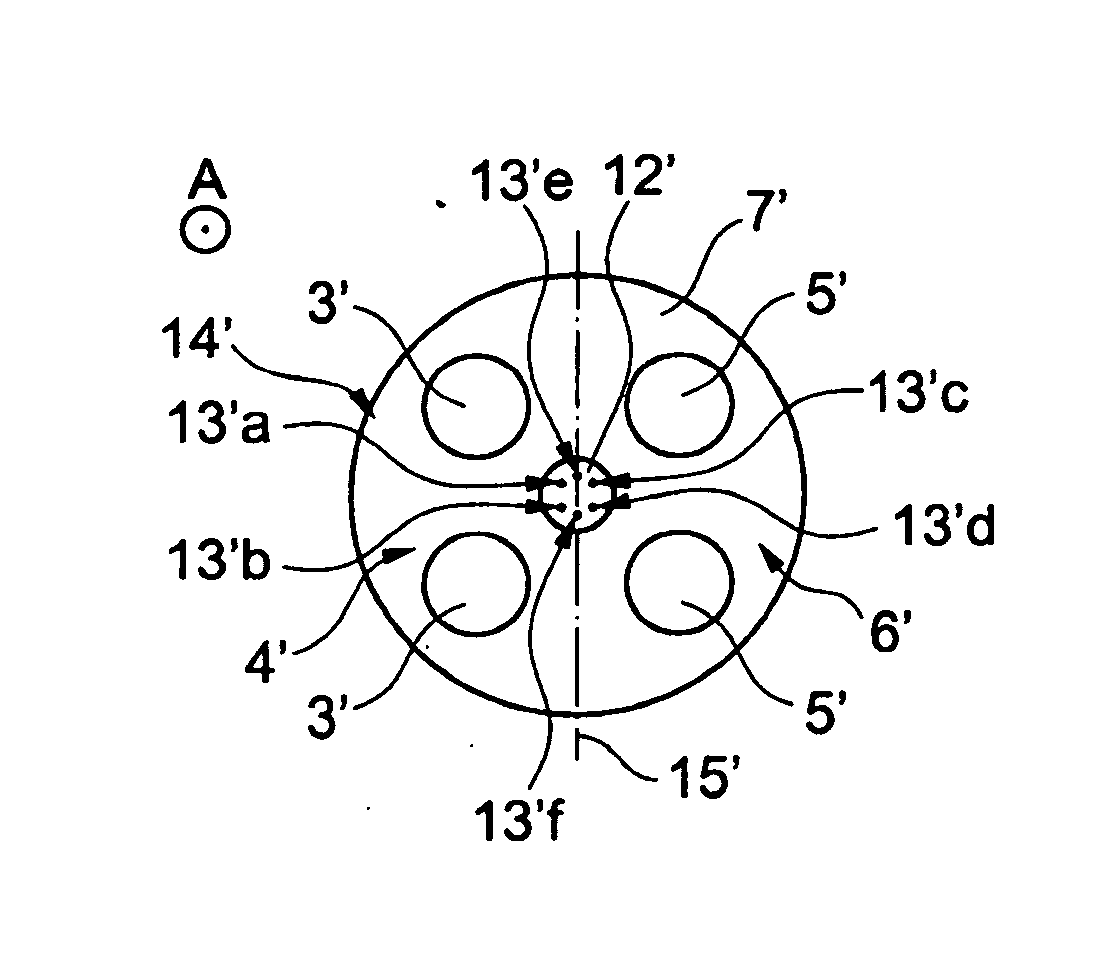
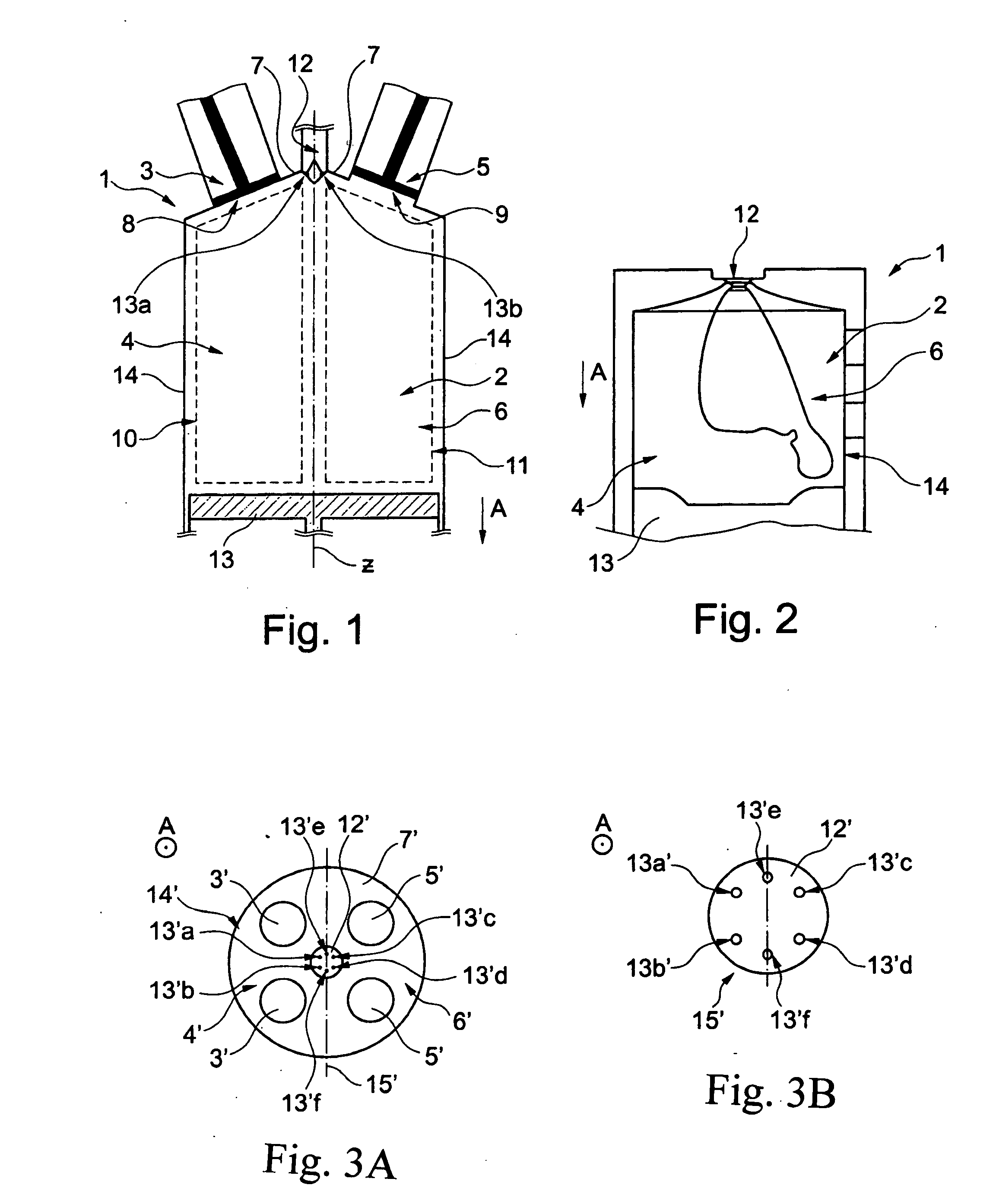
[0024]The illustration in FIG. 1 shows a longitudinal section of a cylinder of a fuel injection system according to the invention of an internal combustion engine, depicted in a roughly schematic manner and denoted by reference numeral 1. The fuel injection system 1 includes a combustion chamber 2 having an intake valve 3 on an intake side 4 of the combustion chamber 2, and an exhaust valve 5 on an exhaust side 6 of the combustion chamber 2. A piston 13 which is movable up and down is situated in the combustion chamber 2. The combustion chamber 2 customarily has a cylindrical design, and is delimited by the cylinder head forming an end face 7. The cylinder head includes intake valve receiving opening 8 and an exhaust valve receiving opening 9 which are closed by the intake valve 3 and the exhaust valve 5, respectively.

[0025]From the intake side 4 and the exhaust side 6, volume areas 10, 11 (see dashed lines in FIG. 1) of the combustion chamber 2 extend away from the intake valve rec...


PUM


Abstract

In a fuel injection system of an internal combustion engine, having a combustion chamber with at least one intake valve at an intake side and with at least one exhaust valve at an exhaust side of the combustion chamber and a central injection nozzle for injecting fuel into the combustion chamber, the injection nozzle has injection orifices which are designed and oriented in such a way that a first quantity of fuel is injected into the intake side, a second quantity of fuel injected is into the exhaust side, and a third quantity of fuel which is about equal to the first quantity and greater than the second quantity is injected into a boundary area between the intake and the exhaust sides, providing for a low-emission operation of the internal combustion engine.

Description

[0001]This is a Continuation-In-Part application of pending international patent application PCT / EP2013 / 002786 filed 2013 Sep. 14 and claiming the priority of German patent application 10 2012 018 780.7 filed 2012 Sep. 22.BACKGROUND OF THE INVENTION[0002]The invention relates to a fuel injection system of an internal combustion engine, and an internal combustion engine having such a fuel injection system.[0003]In gasoline engines with direct fuel injection, the aim is to achieve the best possible distribution of the fuel in the combustion chamber and efficient, low-emission combustion of the fuel-air mixture in a so-called homogeneous operation of the internal combustion engine by means of the injection nozzles. For this purpose, in conventional fuel injection systems, injectors in the form of injection nozzles are usually used which open inwardly and generate a conical spray. Such injection nozzles customarily have five to seven injection orifices. To achieve good atomization of th...

Claims


Application Information

Patent Timeline
Patent Type & Authority Applications(United States)
IPC IPC(8): F02M61/18F02M61/14
CPCF02M61/1813F02M61/1846F02M61/14F02B23/101F02B2023/103F02B2023/106F02M61/1853F02M69/045Y02T10/12
Inventor KADEN, ARNOLDKARL, GUENTERROESSLER, KLAUS
Owner DAIMLER AG
Why Eureka
Try Eureka