Method and device for activating a valve of a fuel vapor retention system

a fuel vapor retention and valve activation technology, which is applied in the direction of domestic cooling devices, electric control, instruments, etc., can solve the problems of increasing pollutant emissions and affecting so as to improve the opening behavior of the valve, reduce or prevent the effect of disturbance in the operation of combustion engines

Active Publication Date: 2007-07-19
VITESCO TECH GERMANY GMBH
View PDF18 Cites 3 Cited by
  • Summary
  • Abstract
  • Description
  • Claims
  • Application Information

AI Technical Summary

Benefits of technology

[0008] The invention is based on the finding that the valve of the fuel vapor retention system, in the case of a first opening event at the start of the determination phase following an interruption in operation that exceeds the predefined threshold value and during which the valve is closed, only opens where relevant if the valve, by deviation from an otherwise valid control characteristic for the valve, is activated with a stronger control signal. This corresponds to a “sticking” of the valve in its closed position. As a result, the valve remains closed at the start of the determination phase, although it should already be opened, and opens abruptly upon activation with the stronger control signal with an opening level due to which, depending on the fuel vapor loading level of the fuel vapor retention system, too great a quantity of fuel vapor is fed, where relevant, to the combustion engine. This can result in an impairment of the operation of the combustion engine and an increase in pollutant emissions. Providing the conditioning pulse prior to the determination phase improves the opening behavior of the valve for the following determination phase, with the result that said phase can be effected reliably and precisely. Furthermore, a disturbance in the operation of the combustion engine can be reduced or prevented by a suitable configuration of the conditioning pulse, with the result that a reliable, low-pollution operation of the combustion engine is possible.
[0009] In an advantageous embodiment of the invention, the predefined opening period of the valve in the case of the conditioning pulse comprises at most 100 milliseconds. This has the advantage that the quantity of fuel vapor flowing at most through the valve during the opening period of the valve is small and as a result only a small disturbance in the operation of the combustion engine can be caused.
[0010] In a further advantageous embodiment of the invention, the predefined first period comprises approximately between 0.5 and 15 seconds. This has the advantage that any disturbance in the operation of the combustion engine can be reliably corrected during the predefined first period, said disturbance being caused by the quantity of fuel vapor that is fed additionally, where relevant, to the combustion engine on the basis of the conditioning pulse.
[0011] In a further advantageous embodiment of the invention, the predefined threshold value comprises at least 30 seconds. This has the advantage that the valve is only activated with the conditioning pulse if there is a high risk of a possible impairment of the opening behavior of the valve at the start of the determination phase. This risk rises with the second period during which the valve is closed uninterruptedly. It is particularly advantageous to activate the valve with the conditioning pulse at the first opening after a start-up of operation of the combustion engine.

Problems solved by technology

This can result in an impairment of the operation of the combustion engine and an increase in pollutant emissions.

Method used


Image

  • Method and device for activating a valve of a fuel vapor retention system
  • Method and device for activating a valve of a fuel vapor retention system
  • Method and device for activating a valve of a fuel vapor retention system

Examples


Embodiment Construction

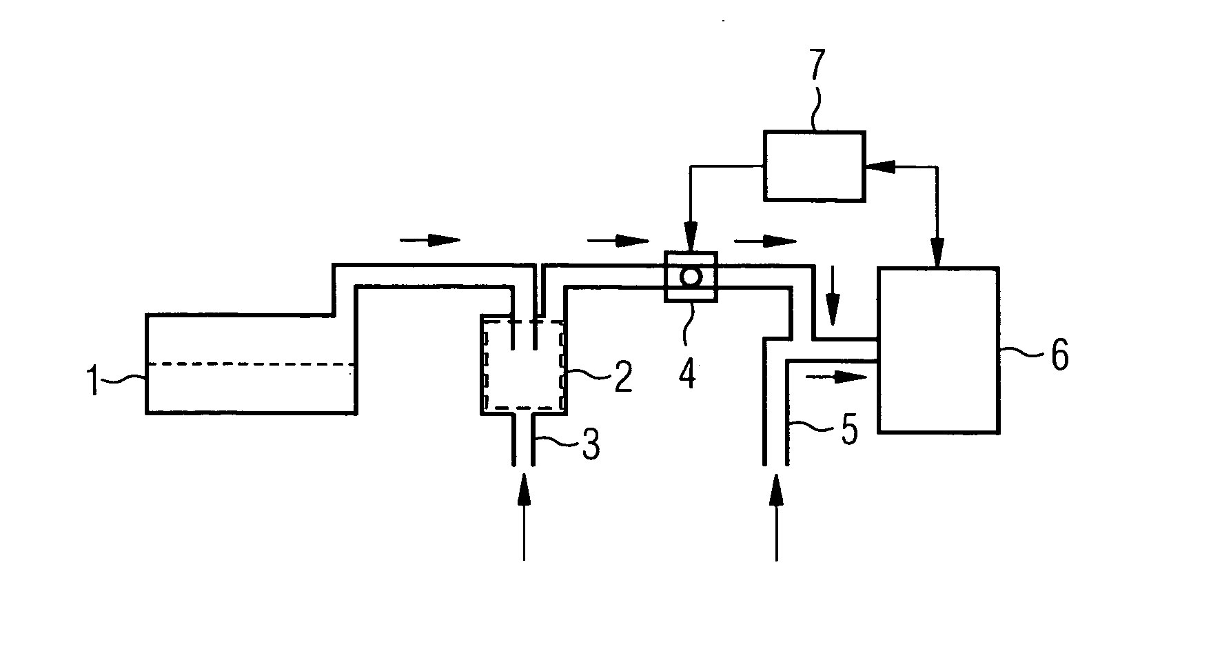
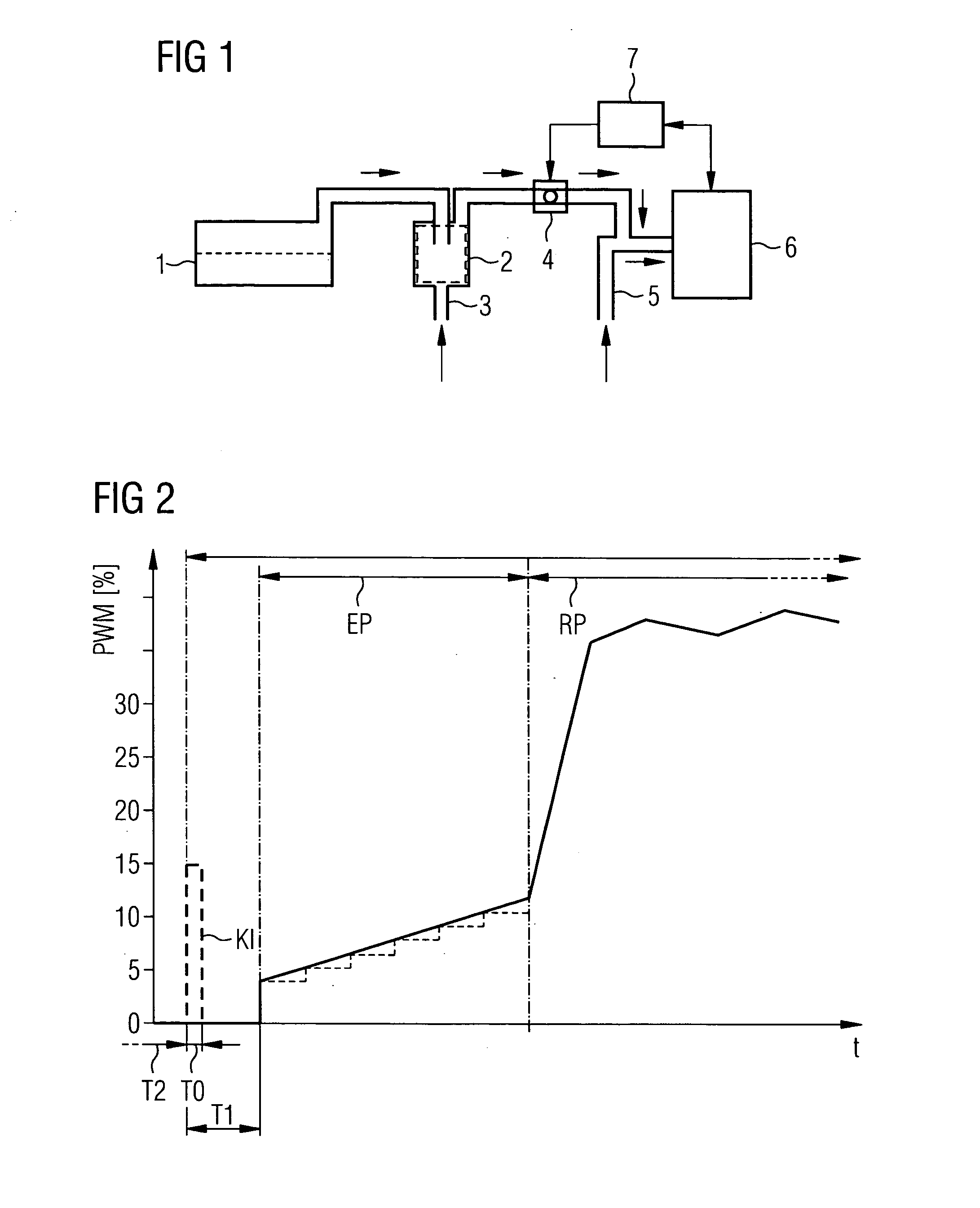
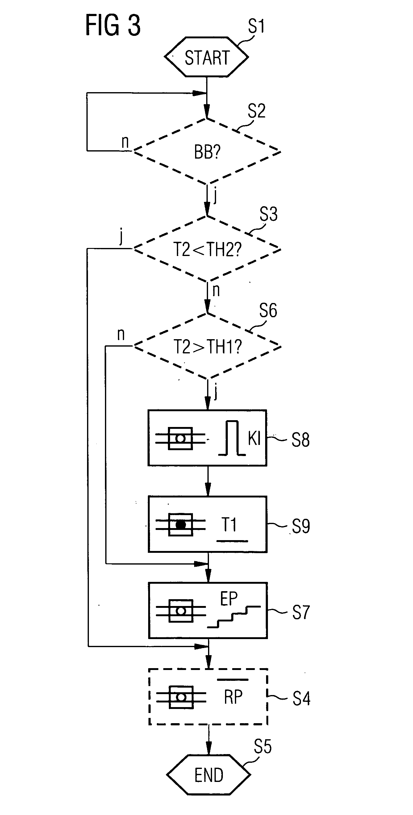
[0014] A fuel vapor retention system comprises a fuel vapor retention filter 2 with a fresh-air feed 3 and a valve 4 (FIG. 1). The fuel vapor retention filter 2 is coupled to a fuel tank 1 on the input side. Fuel vapor that collects in the fuel tank 1 due to evaporation of the fuel in the fuel tank 1 is fed to the fuel vapor retention filter 2. The fuel vapor retention filter 2 displays a storage medium for fuel vapor which comprises e.g. activated carbon. The fuel vapor retention filter 2 is coupled on the output side, via the valve 4, to a suction pipe 5 of a combustion engine 6.

[0015] Furthermore, a control unit 7 is provided that is coupled to the valve 4 and that is configured to feed a control signal to said valve for opening and closing the valve 4. The control signal is, for example, pulse-width modulated and a PWM value of the control signal is predefined by an associated pulse width. However, the control signal can also be configured differently.

[0016] The control unit 7...


PUM


Abstract

For the purposes of a determination of a fuel vapor loading level of a fuel vapor retention system of a combustion engine, an opening level of a valve of the fuel vapor retention system is increased in steps or continuously during a determination phase. Furthermore, the valve is activated at most a predefined first period prior to a start of the determination phase by a conditioning pulse at least whenever the valve was closed previously for a second period that is longer than a predefined threshold value. The conditioning pulse is generated in such a way that the valve definitely opens at most for a predefined opening period and then closes again.

Description

CROSS REFERENCE TO RELATED APPLICATIONS [0001] This application claims priority of German application No. 10 2006 002 717.5filed Jan. 19, 2006, which is incorporated by reference herein in its entirety. FIELD OF INVENTION [0002] The invention relates to a method and a corresponding device for activating a valve of a fuel vapor retention system of a combustion engine for the purposes of a determination of a fuel vapor loading level of the fuel vapor retention system. BACKGROUND OF THE INVENTION [0003] A fuel vapor retention system is disclosed, for example, in van Basshuysen & Schäfer, “Handbuch Verbrennungsmotor”, 2nd edition, Vieweg Verlag, 2002, pages 604 to 607. Such a fuel vapor retention system is provided within a motor vehicle, for example, in order to absorb and store fuel vapor that forms in a fuel tank due to evaporation, with the result that the fuel vapor cannot escape into the environment. A fuel vapor retention filter is provided within the fuel vapor retention system ...

Claims


Application Information

Patent Timeline
Patent Type & Authority Applications(United States)
IPC IPC(8): F02M25/08
CPCF02D41/004F02D41/2438F02M25/0836F02D2041/2027F02D2041/2055F02D41/2464A47F3/0469A47F3/0482A47F11/00F25D23/067F25D2201/12
Inventor LUDWIG, WOLFGANGMAI, WOLFGANGPACHE, JENS
Owner VITESCO TECH GERMANY GMBH
Why Eureka
Try Eureka