
Internal Combustion Engine And Method For Controlling The Operation Of The Internal Combustion Engine

a technology of internal combustion engine and internal combustion engine, which is applied in the direction of position/direction control, braking system, analog and hybrid computing, etc., can solve the problems reducing the operating cost and unable to completely avoid the drop in the rotational speed of the internal combustion engine. , to achieve the effect of reducing the rotational speed of the internal combustion engine and the energy consumption of the assist system, reducing

Active Publication Date: 2013-06-06
MAN ENERGY SOLUTIONS SA
View PDF10 Cites 0 Cited by
  • Summary
  • Abstract
  • Description
  • Claims
  • Application Information

AI Technical Summary

Benefits of technology

The invention provides a method for controlling an internal combustion engine that can quickly and efficiently increase its power output when needed. This is done by modifying a standard control map based on the operating load of the engine, which results in a higher ignition pressure and increased fuel injection. This method can reduce the energy consumption of the assist system and prevent an increase in pollutant emissions, leading to a more compact and cost-effective engine.

Problems solved by technology

However, the use of a compressed-air assist system leads to an appreciable increase in the operating costs of the internal combustion engine due to its consumption of compressed air.
Further, a compressed-air assist system of this kind also requires a certain period of time for accelerating the compressor impeller in the desired manner, and a drop in rotational speed of the internal combustion engine can accordingly not be completely averted.

Method used


Image

  • Internal Combustion Engine And Method For Controlling The Operation Of The Internal Combustion Engine
  • Internal Combustion Engine And Method For Controlling The Operation Of The Internal Combustion Engine

Examples


Embodiment Construction

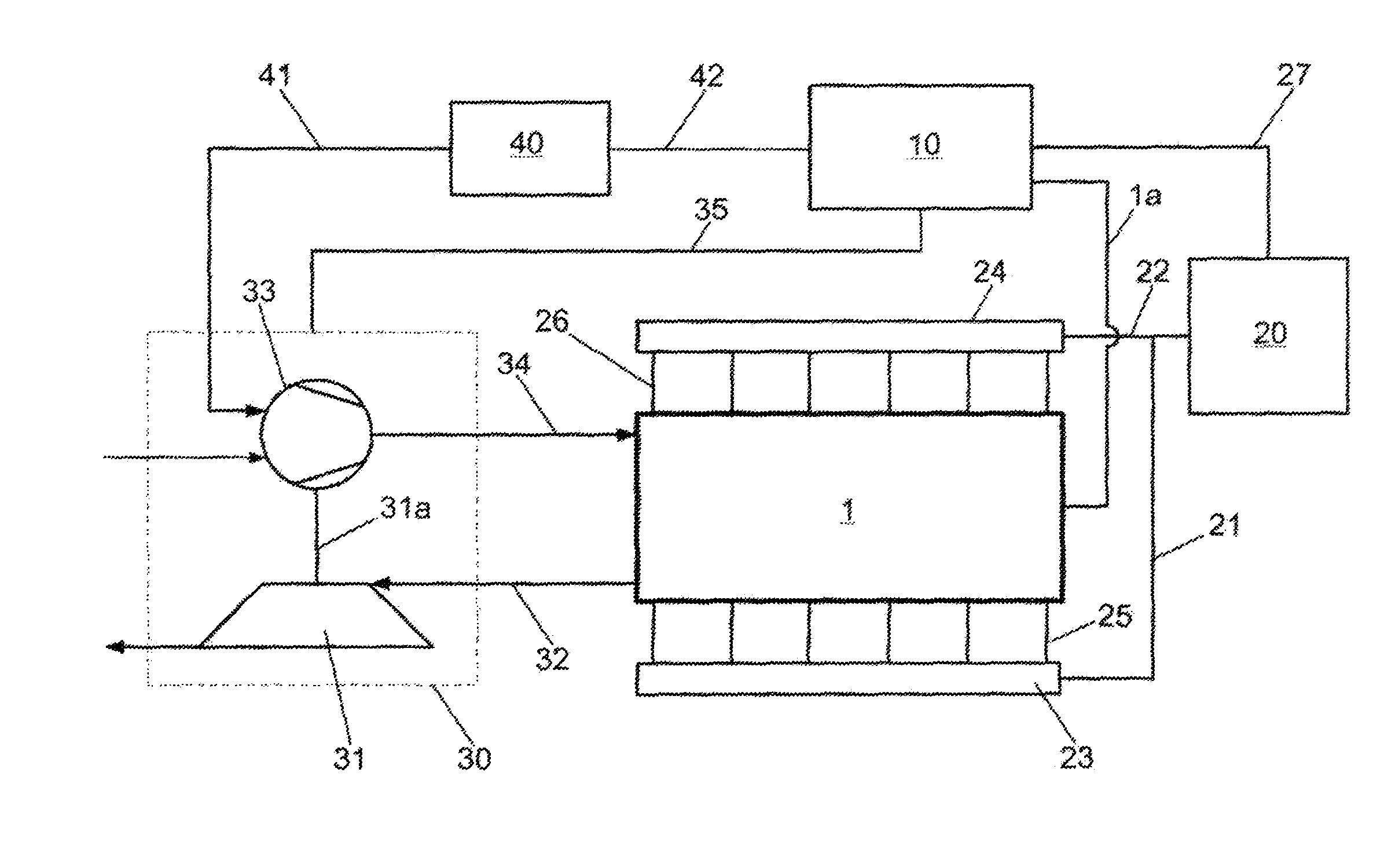
[0030]The internal combustion engine 1 shown in FIG. 1 is a large-capacity diesel engine (in this case, e.g., a 12 cylinder V-type engine) for operating (propulsion and / or power generation) a ship (not shown).

[0031]The internal combustion engine 1 has a control apparatus 10, a common rail fuel injection system 20, an exhaust gas turbocharger 30 for pressure charging an air quantity provided for combustion in the internal combustion engine 1, and a compressed-air assist system 40 for rapidly increasing the air quantity supplied by the exhaust gas turbocharger 30 during a sudden increase in an operating load (operating load cut-in) of the internal combustion engine 1.

[0032]An increase of this kind in the operating load of the internal combustion engine 1 by a predetermined extent can be brought about, e.g., by an increase in thrust or increase in speed of the ship initiated from the bridge of the ship or, e.g., in a diesel-electric system, also due to sudden switching on of a relevant...


PUM


Abstract

Internal combustion engine and method for controlling the operation of an internal combustion engine, wherein the method comprises: determining an operating load of the internal combustion engine, controlling the operation of the internal combustion engine on the basis of a standard control map which realizes a determined propulsion power of the internal combustion engine when the operating load of the internal combustion engine is constant and, when the operating load of the internal combustion engine increases to a predetermined extent, activating at least one control characteristic for modifying the standard control map so that the propulsion power of the internal combustion engine is increased.

Description

PRIORITY CLAIM[0001]This is a U.S. national stage of application No. PCT / DE2011 / 050000, filed on Jan. 24, 2011. Priority is claimed on the following application(s): Country: Germany, Application No.: 10 2010 003 736.2, Filed: Apr. 8, 2010, the content of which is / are incorporated herein by referenceBACKGROUND OF THE INVENTION[0002]1. Field of the Invention[0003]The invention is directed to an internal combustion engine and to a method for controlling the operation of the internal combustion engine.[0004]2. Background of the Invention[0005]Internal combustion engines such as common rail diesel engines, for example, have for controlling the operation thereof various control maps which are optimized for a stationary operation (operation of the internal combustion engine without a sudden change in operating load or increase in operating load).[0006]At present, in exhaust-gas turbocharged internal combustion engines a compressed-air assist system is used to increase the rotational speed ...

Claims


Application Information

Patent Timeline
Patent Type & Authority Applications(United States)
IPC IPC(8): F02D41/34
CPCF02B21/00F02B29/02F02D29/02F02D41/0007F02D41/3836F02D41/34F02D2250/31Y02T10/146Y02T10/44Y02T10/144F02D41/401Y02T10/12Y02T10/40F02D41/04F02D41/40
Inventor ADORF, SONJAHOLAND, PETERNUTTO, JOACHIM
Owner MAN ENERGY SOLUTIONS SA
Learn More