Air outlet device and air fan

A technology for air outlet devices and fans, which is applied to pump devices, parts of pumping devices for elastic fluids, and non-variable pumps, etc. It can solve the problems of low air volume and wind speed of fans, and achieve short acceleration time, Optimized wind performance and high wind speed

Pending Publication Date: 2019-12-13
XUXIN ELECTRICAL TECH (SHENZHEN) CO LTD
View PDF0 Cites 0 Cited by
  • Summary
  • Abstract
  • Description
  • Claims
  • Application Information

AI Technical Summary

Problems solved by technology

[0004] The object of the present invention is to provide an air outlet device and a fan to overcome the defects of low air volume and wind speed of the fan

Method used


Image

  • Air outlet device and air fan
  • Air outlet device and air fan
  • Air outlet device and air fan

Examples


no. 1 example

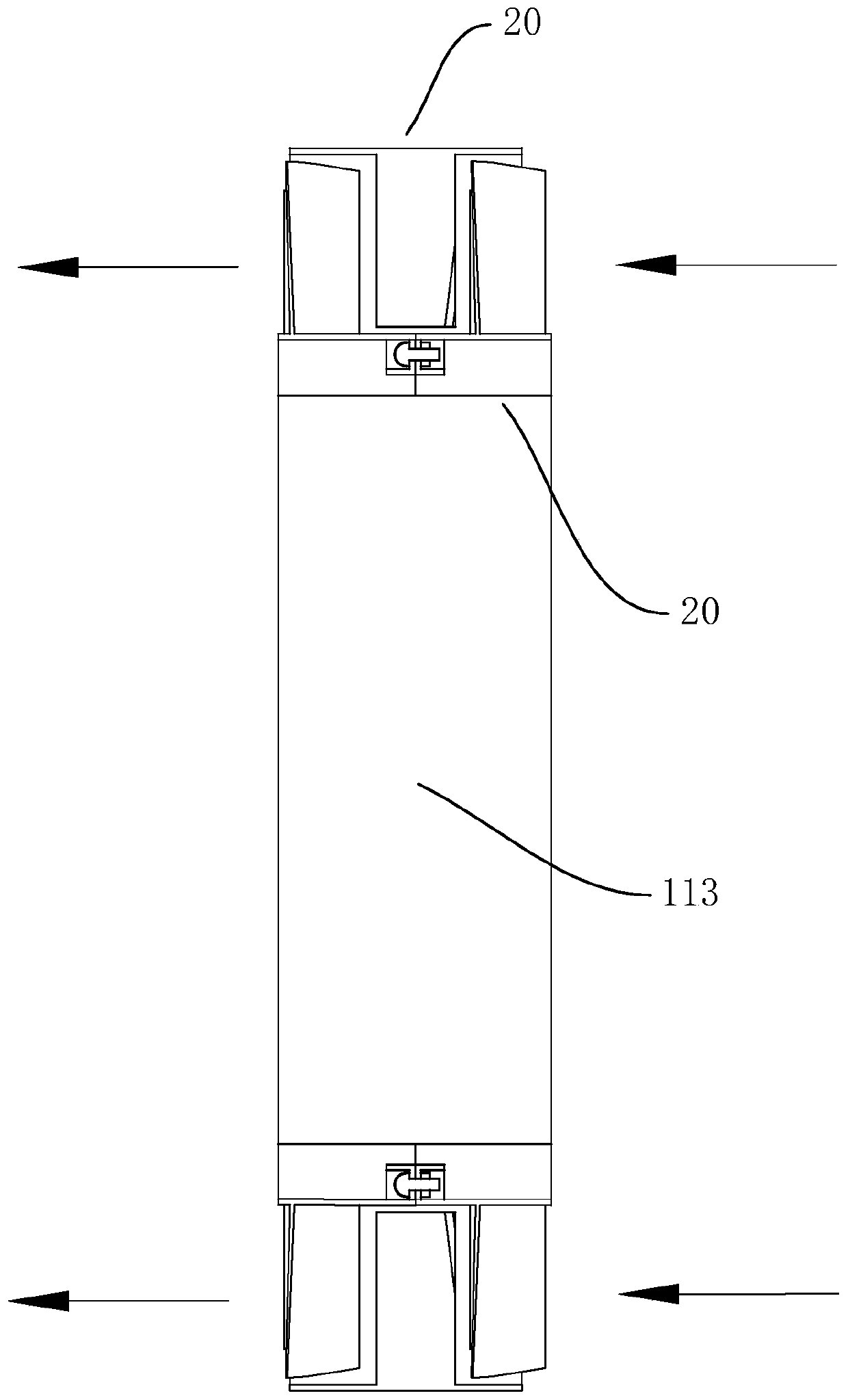
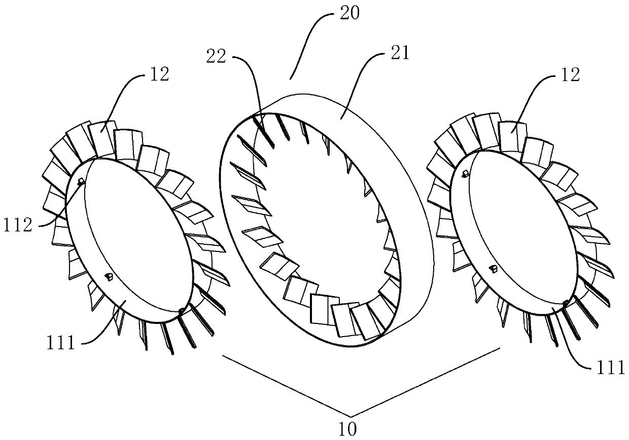
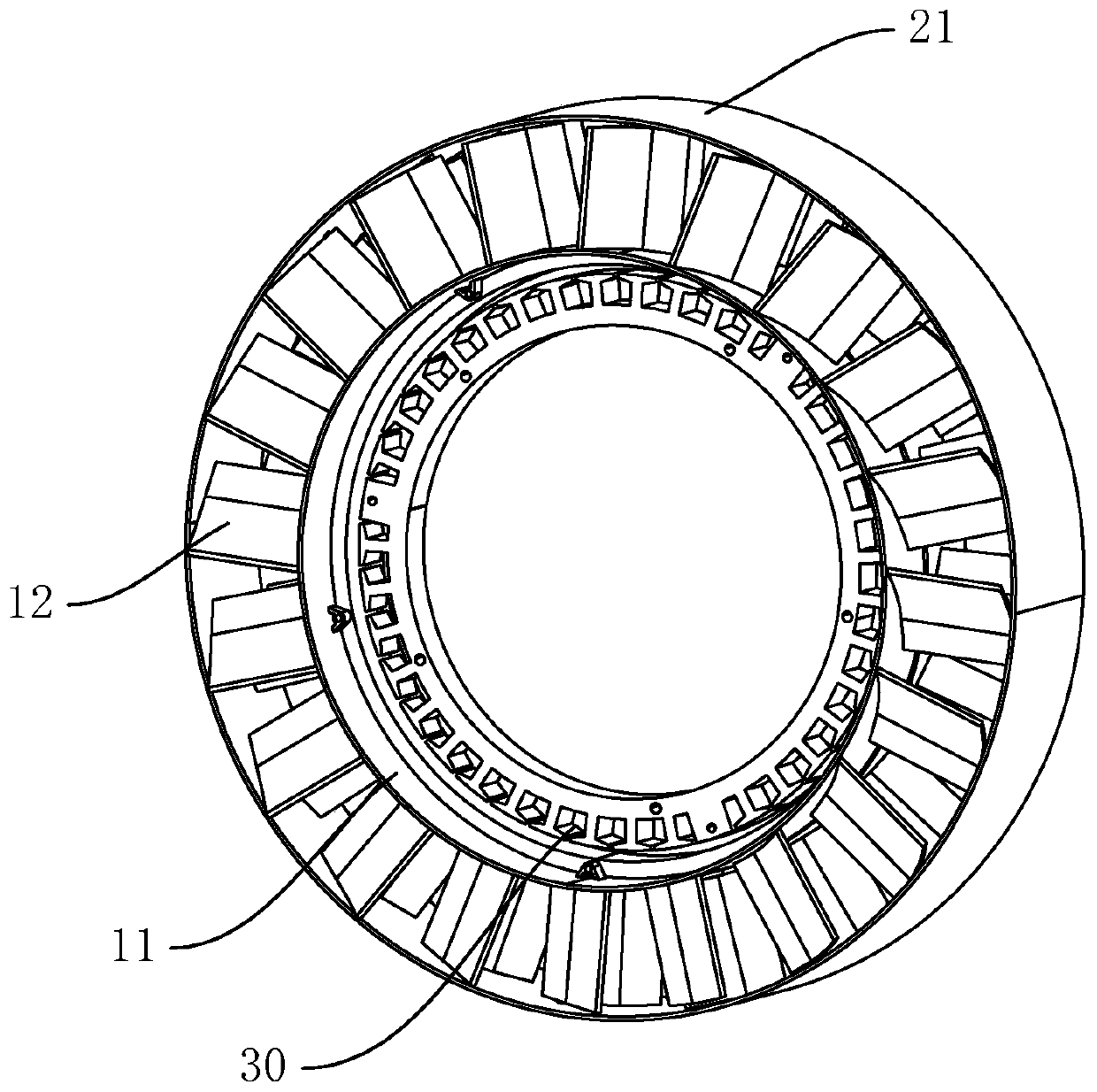
[0033] refer to Figure 1 to Figure 4 , the air outlet device in this embodiment includes a first air outlet 10 and a second air outlet 20, the first air outlet 10 and the second air outlet 20 are arranged alternately in sequence, and the first air outlet 10 includes a first air outlet The base 11 has a number of first fan blades 12 arranged along the edge of the first base 11; the second air outlet 20 includes a second base 21, and a number of second fan blades 22 are arranged along the edge of the second base 21. The blades 12 and the second blades 22 are alternately arranged in sequence along the axial direction of the first base body 11 or the second base body 21, the direction of the windward side of the adjacent first blades 12 and the second blades 22 is opposite, and the first air outlet part 10 It can be rotated relative to the second air outlet part 20 .

[0034] Because the first fan blades 12 and the second fan blades 22 are arranged alternately in sequence, and t...

no. 2 example

[0045] refer to Figure 5 The difference between this embodiment and the first embodiment is that the second base 21 includes no less than two second units 211, two adjacent second units 211 are docked and detachably connected, and multiple first units 111 are sequentially connected along the arrangement direction of the first fan blades 12 and the second fan blades 22 to form the second base body 21 , and the inner surface of each second unit 211 is connected with the second fan blades 22 . By segmenting the second base body 21, the installation difficulty of the air outlet device is further reduced. Several second installation blocks 212 can be arranged along the outer surface of the second base body 21, second installation blocks 212 are provided with second installation holes, the connection between the second installation blocks 212 is the same as the connection between the first installation blocks 112 the same way.

[0046] Preferably, no less than two rows of first f...

no. 3 example

[0048] refer to Figure 6 The difference between this embodiment and the second embodiment is that the first base body 11 and the second base body 12 are spliced ​​structures, the first base body 11 is composed of three first units 111, and each first unit 111 has a A row of first fan blades 12 is connected, the second base body 21 is composed of two first units 211, and each second unit 211 is connected with a row of second fan blades 22, the first fan blades 12 and the second fan blades 22 alternate arrangements. By arranging both the first base body 11 and the second base body 21 in a spliced ​​structure, the convenience of processing and assembling the air outlet device is further improved, and the production cost is reduced.


PUM


Abstract

The invention relates to an air outlet device and an air fan. The air outlet device comprises a first air outlet part and a second air outlet part, a second base body sleeves the outer part of a firstbase body, a plurality of first fan blades are extended to the second base body based on the first base body surface, a plurality of second fan blades are extended to the first base body based on thesecond base body surface, the orientation of the windward sides of the adjacent first fan blades is opposite to the orientation of the windward sides of the second fan blades, and the first air outlet part and the second air outlet part can rotate relatively; and the air fan comprises the air outlet device. Because the direction of the windward sides of the first fan blades is opposite to the direction of the windward sides of the second fan blades, after the outside air enters the air outlet device, the first fan blades and the second fan blades sequentially push the air forward in the samedirection to form air flow, the speed of the air flow gradually increases in the flowing direction of the air, thus the air can quickly enter from one side of the air outlet device, and be dischargedfrom the other side of the air outlet device, acceleration time of the air flow is short, the air outlet volume is large, the air speed is high, and the air outlet performance of the air outlet deviceis optimized.

Description

technical field [0001] The invention relates to the technical field of air outlet appliances and fans, in particular to an air outlet device and a fan. Background technique [0002] Fans, as the main electrical appliances for air circulation and cooling, are widely used in homes, schools, offices and other places. [0003] Traditional fans generally drive the blades to rotate, and the blades push the air to form an airflow to achieve air flow. The air volume and wind speed blown out by this air outlet method are limited. In order to meet the demand for air volume and wind speed, the power of the fan needs to be increased. The noise generated by the work increases with the increase of the fan speed and reduces the working efficiency of the fan. Contents of the invention [0004] The object of the present invention is to provide an air outlet device and a fan, so as to overcome the defects of low air volume and wind speed of the fan. [0005] The technical solution adopted...

Claims


Application Information

Patent Timeline
Patent Type & Authority Applications(China)
IPC IPC(8): F04D17/04F04D25/08F04D25/16F04D29/26F04D29/42
CPCF04D17/04F04D25/0613F04D25/08F04D25/166F04D29/281F04D29/4226
Inventor 张平周慧珠孙兴林孙叶琳骆兰英
Owner XUXIN ELECTRICAL TECH (SHENZHEN) CO LTD
Why Eureka
Try Eureka