Active roll-rod for vehicle

a technology of active rollers and rolling rods, which is applied in the direction of machine supports, jet propulsion mountings, other domestic objects, etc., can solve the problems of low efficiency, small space, and generated vibration, and achieve the effect of efficient attenuation

Active Publication Date: 2015-07-23
HYUNDAI MOTOR CO LTD
View PDF13 Cites 21 Cited by
  • Summary
  • Abstract
  • Description
  • Claims
  • Application Information

AI Technical Summary

Benefits of technology

[0020]In the present invention, the damper unit, which cancels vibratory force of an engine, is embedded in the roll rod, and as a result, there are effects in that the roll rod may be mounted without changing a structure of the sub-frame, and vibration, which is transmitted to a vehicle body, may be more efficiently attenuated depending on a driving state of a vehicle.

Problems solved by technology

More particularly, in the case of the engine mount 8a or the transmission mount 9a that is configured in a block shape and seated on the vehicle body, the active damper is embedded therein or a separate damper is additionally mounted in the vicinity thereof such that vibration generated in the engine may be more efficiently attenuated, but in the case of the roll rod, the steering device, the suspension device, and the like are seated on the sub-frame, which causes a space to become small, and as a result, there is a problem in that it is difficult to additionally mount the damper.
In addition, there occurs a difference in displacement between the roll rod and the vehicle body by an operation of the power train due to the generation of vibration of a vehicle even though a space for additionally mounting the damper in the vicinity of the roll rod is provided in the sub-frame, and as a result, there is a problem in that interference due to the aforementioned configuration needs to be avoided.
In the case of the roll rod, it is very difficult to configure a hydraulic structure in which a hydraulic fluid is sealed as a working fluid, and as a result, there is a problem in that a size of the roll rod is increased when the damper is added because the size of the roll rod becomes very large even if the hydraulic structure is applied.

Method used


Image

  • Active roll-rod for vehicle
  • Active roll-rod for vehicle
  • Active roll-rod for vehicle

Examples


Embodiment Construction

[0028]Reference will now be made in detail to various embodiments of the present invention(s), examples of which are illustrated in the accompanying drawings and described below. While the invention(s) will be described in conjunction with exemplary embodiments, it will be understood that present description is not intended to limit the invention(s) to those exemplary embodiments. On the contrary, the invention(s) is / are intended to cover not only the exemplary embodiments, but also various alternatives, modifications, equivalents and other embodiments, which may be included within the spirit and scope of the invention as defined by the appended claims.

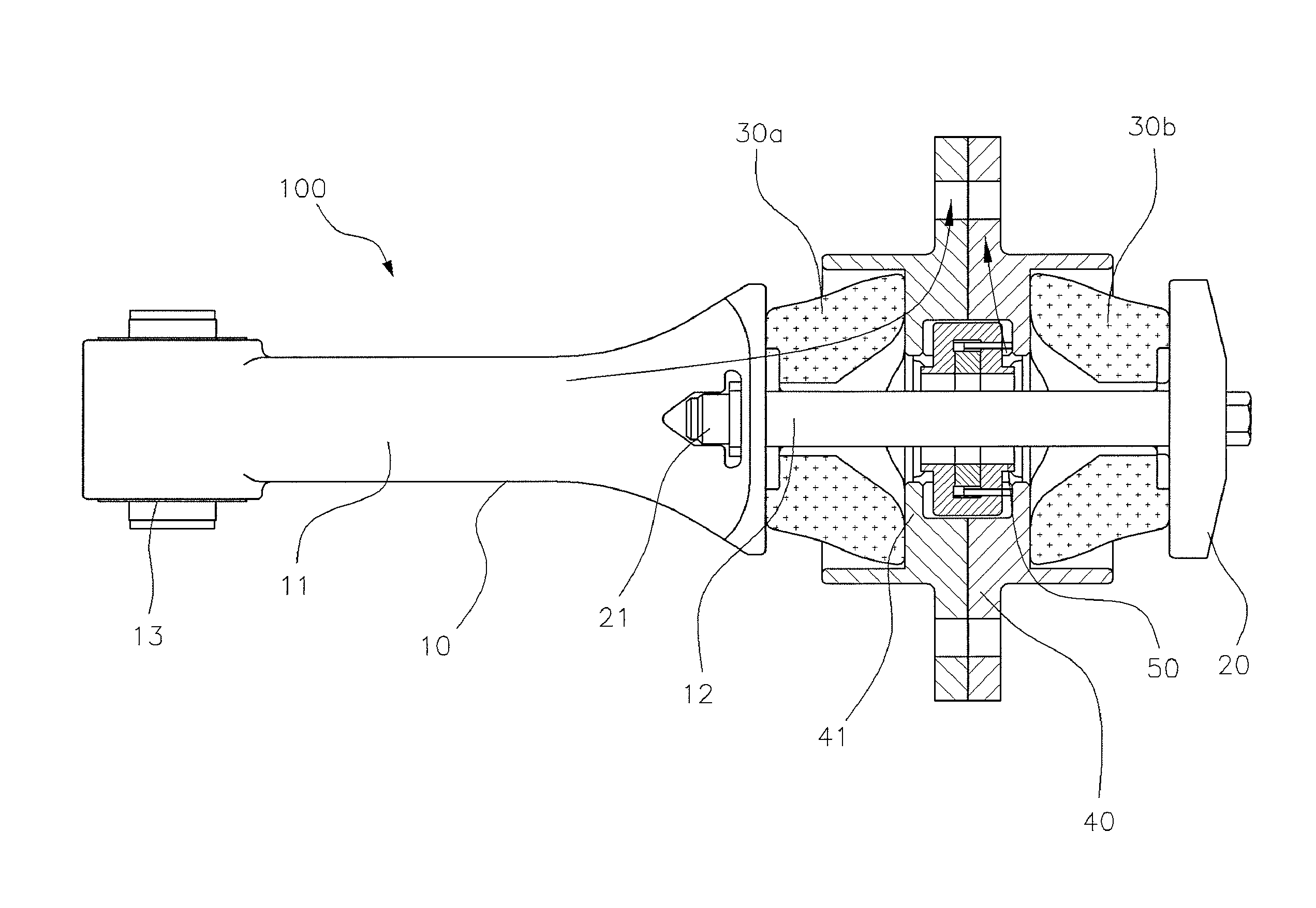
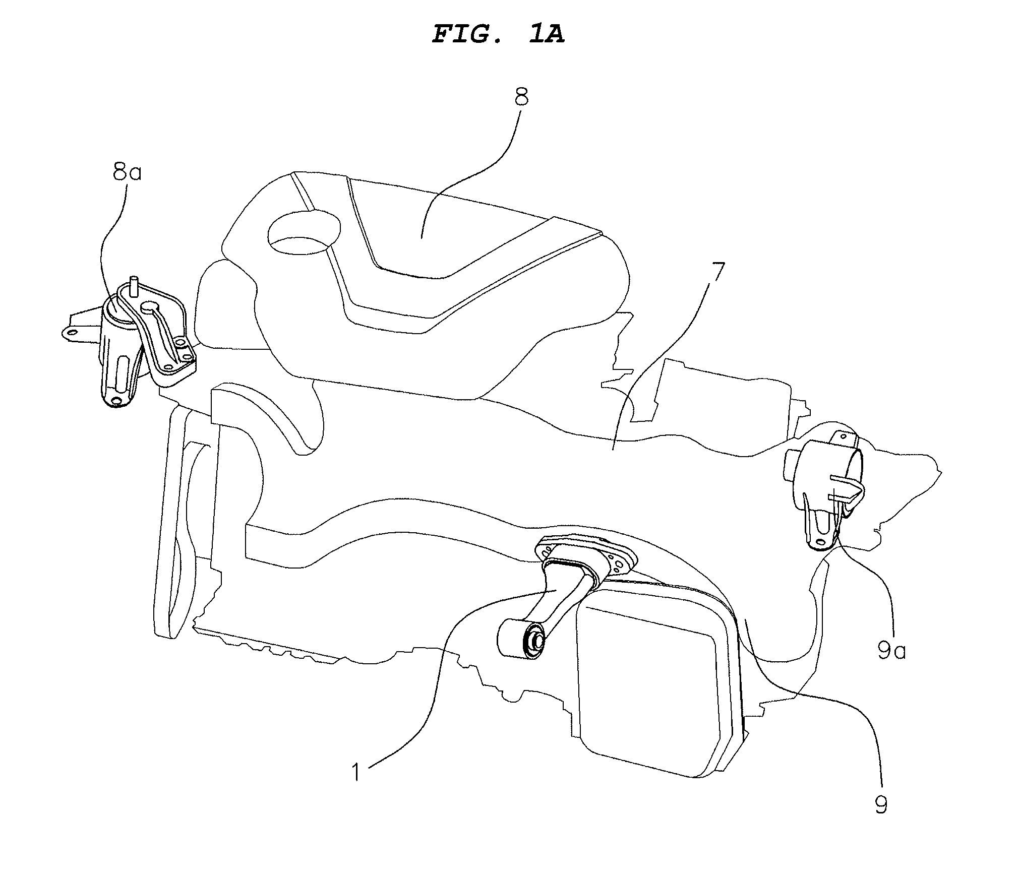
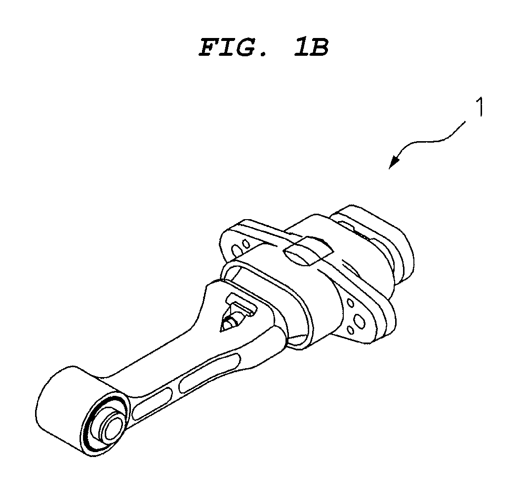
[0029]A roll rod for a vehicle of the present invention is mounted to connect a power train, which is configured by coupling an engine and a transmission, with a sub-frame (to which a suspension device and a steering device are mounted, and which is coupled to a vehicle body). Hereinafter, the roll rod for a vehicle according to vario...


PUM

PropertyMeasurementUnit
diameteraaaaaaaaaa
elasticaaaaaaaaaa
electromagnetic forceaaaaaaaaaa

Abstract

An active roll rod for a vehicle may include a rod portion, a fastening unit, insulators, an end plate and a damper unit. The rod portion may have a main body portion with a front end connected to a power train, and an inner pipe formed at a rear side of the main body portion. The fastening unit may be mounted to a sub-frame, slidably coupled to the inner pipe and have a partition wall portion formed on an inner circumferential surface. The insulators may be mounted at front and rear sides of the partition wall portion and made of an elastic material. The end plate may be coupled to a rear end of the inner pipe. The damper unit may have a cooperating unit on which a permanent magnet is mounted, and a coil portion which generates electromagnetic force and controls an operation of the cooperating unit. The damper unit may be embedded in the fastening unit.

Description

CROSS-REFERENCE TO RELATED APPLICATIONS[0001]The present application claims priority of Korean Patent Application Number 10-2014-8150 filed on Jan. 23, 2014, the entire contents of which application are incorporated herein for all purposes by this reference.BACKGROUND OF INVENTION[0002]1. Field of Invention[0003]The present invention relates to an active roll rod for a vehicle, and more particularly, to an active roll rod for a vehicle which has been invented to more efficiently suppress vibration, which is transmitted to a vehicle body, depending on a driving state of a vehicle by embedding a damper unit (which is configured to be able to absorb vibration within an overall frequency region by adjusting a frequency of a current), which serves as an active damper, in a fastening unit that is mounted to a sub-frame.[0004]2. Description of Related Art[0005]In passenger vehicles, a monocoque body, which is light in weight and has excellent productivity, is mainly used instead of a frame...

Claims


Application Information

Patent Timeline
Patent Type & Authority Applications(United States)
IPC IPC(8): F16F6/00B60K5/12
CPCB60K5/1216F16F6/005B60K5/1241B60K5/1283F16F6/00F16F15/03F16F15/08B60K5/12F16F1/36F16F15/02
Inventor YOON, HYOUNG-JINLEE, SANG-IILEE, DONG-WOOK
Owner HYUNDAI MOTOR CO LTD
Why Eureka
Try Eureka