
Pulsation damping device of hydraulic brake system

a technology of hydraulic brake system and damping device, which is applied in the direction of brake system, etc., can solve the problems of difficult manufacturing process, increased cost, and inability to smoothly perform the pressure pulsation attenuation function, and achieves the effect of efficient attenuation of pressure pulsation, simple structure and easy installation

Active Publication Date: 2017-03-02
HL MANDO CORP
View PDF7 Cites 11 Cited by
  • Summary
  • Abstract
  • Description
  • Claims
  • Application Information

AI Technical Summary

Benefits of technology

This patent is about a device that reduces the pulsation of pressure in a hydraulic brake system. The device has a simple structure and is easy to install. The device is efficient in reducing pulsation and helps to improve the performance of the braking system.

Problems solved by technology

However, since a structure for installation of the above-described pulsation damping device is complex, there are problems in that a manufacturing process is difficult and cost is also increased.
Further, since a structure in which the pressure pulsation is attenuated using the spring is formed, there is a problem in that a pressure pulsation attenuation function is not smoothly performed because durability of the spring or the like is degraded when the spring is used for a long time.

Method used


Image

  • Pulsation damping device of hydraulic brake system
  • Pulsation damping device of hydraulic brake system
  • Pulsation damping device of hydraulic brake system

Examples


Embodiment Construction

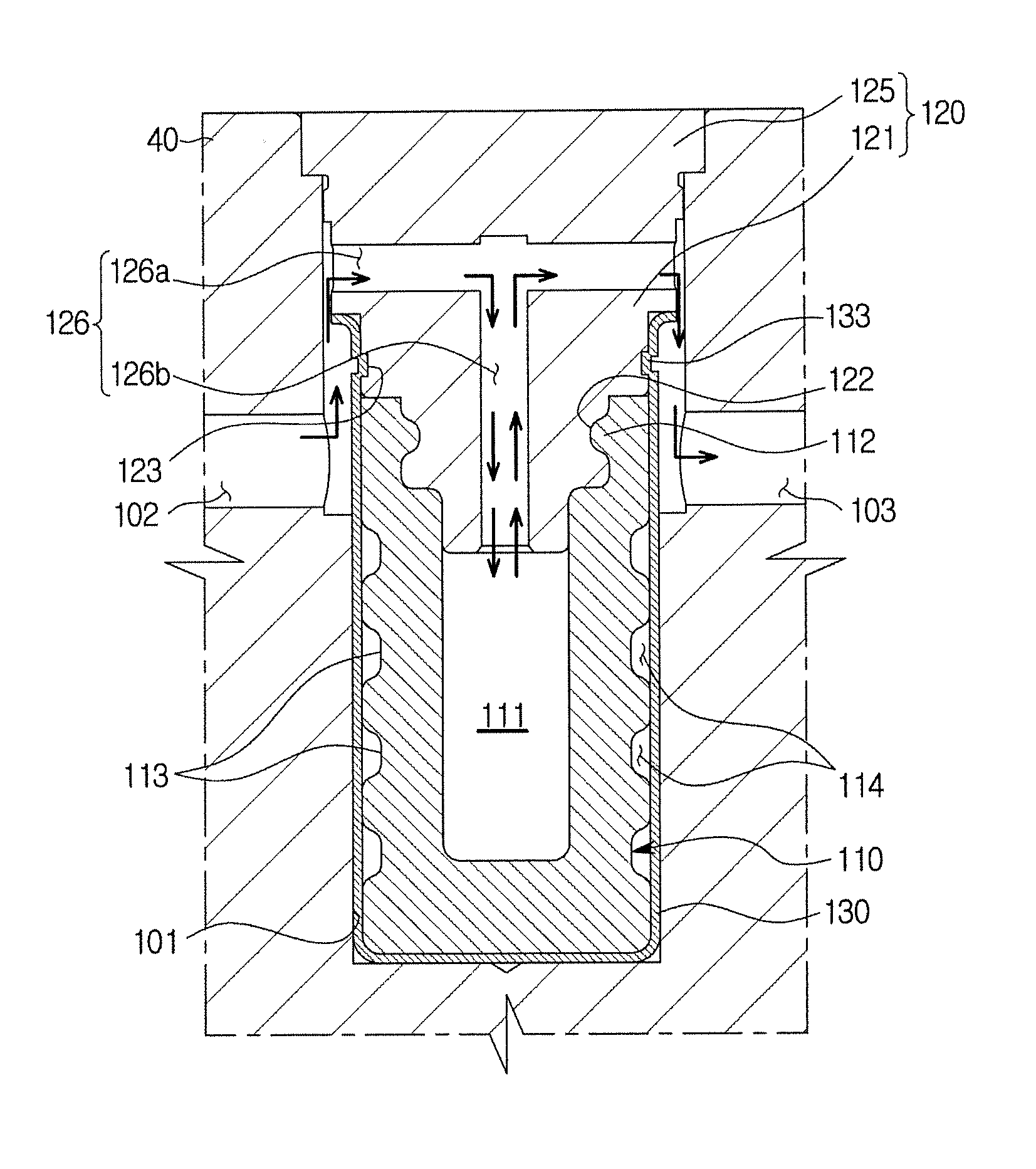
[0027]Hereinafter, embodiments of the present disclosure will be described in detail with reference to accompanying drawings. The accompanying drawings are examples which provide the concept of the present disclosure to those skilled in the art. The present disclosure is not limited to the accompanying embodiments and may be implemented in different forms. Parts irrelevant to description are omitted in the drawings in order to clearly describe the present disclosure, and widths, lengths, and thicknesses of components in the drawings may be exaggerated for convenience of description.

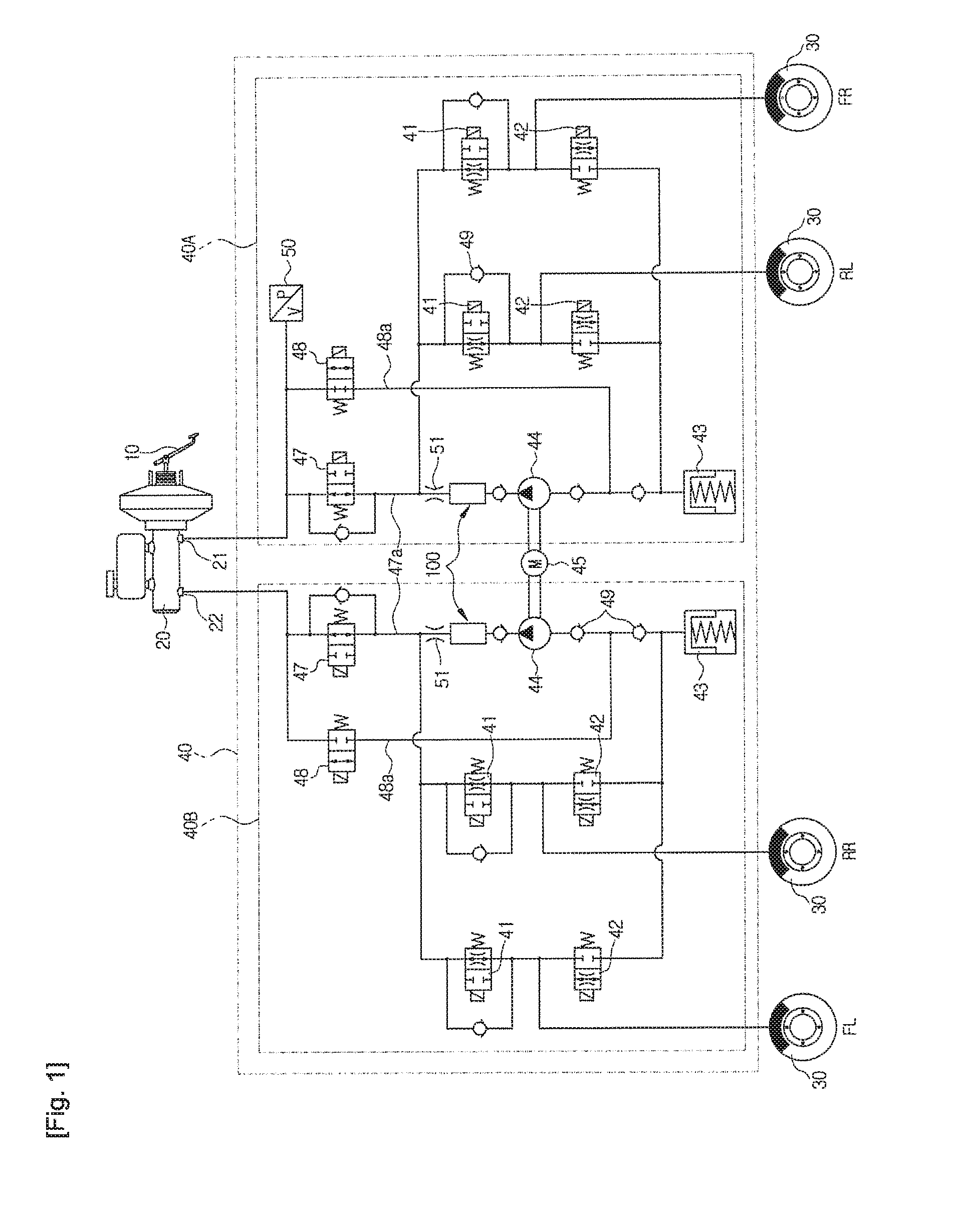
[0028]FIG. 1 is a hydraulic circuit diagram schematically illustrating a hydraulic brake system provided with a pulsation damping device according to an exemplary embodiment of the present disclosure.

[0029]Referring to FIG. 1, the hydraulic brake system includes a brake pedal 10 to which an operating force of a driver is applied, a brake booster 11 which increases pedal effort due to the pedal effort of t...


PUM


Abstract

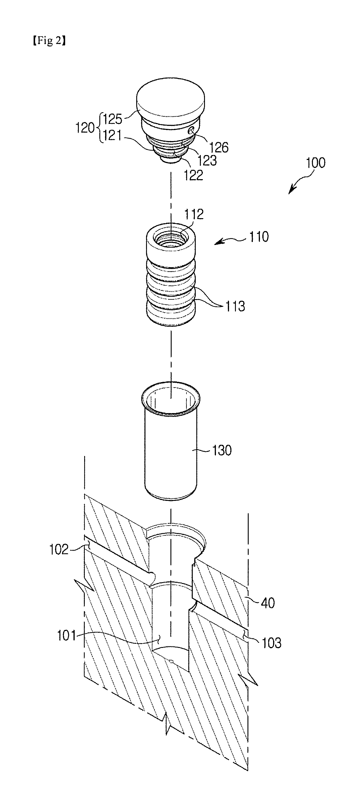
Disclosed herein is a pulsation damping device of a hydraulic brake system. The pulsation damping device of a hydraulic brake system which attenuates a pressure pulsation of brake oil discharged from a pump comprise a sleeve inserted into a bore which communicates with an inport into which the brake oil is introduced and an outport through which the brake oil is discharged, wherein one end of the sleeve is open and the other end is closed, a damping member accommodated in the sleeve and hollowed to form a damping space therein, and a stopper member configured to block one open end of the bore and coupled to an opening of the sleeve.

Description

CROSS-REFERENCE TO RELATED APPLICATION[0001]This application claims the benefit of Korean Patent Application No. 2015-0124029, filed on Sep. 2, 2015 in the Korean Intellectual Property Office, the disclosure of which is incorporated herein by reference.BACKGROUND[0002]1. Field[0003]Embodiments of the present disclosure relate to a hydraulic brake system, and more particularly, to a pulsation damping device of a hydraulic brake system which attenuates a pressure pulsation of brake oil discharged from a pump.[0004]2. Description of the Related Art[0005]In general, in order to control brake hydraulic pressure to be transferred to a brake of a vehicle, a hydraulic brake system includes a modulator block, in which a plurality of solenoid valves, a low pressure accumulator in which oil is temporarily stored, a pump disposed to be connected to an outlet of the low pressure accumulator for pumping the oil stored in the low pressure accumulator, and a motor for driving the pump are installed...

Claims


Application Information

Patent Timeline
Patent Type & Authority Applications(United States)
IPC IPC(8): B60T8/40
CPCB60T8/4068B60T8/4291B60T8/4872
Inventor HER, YOUNG-CHAEJEON, JAE-YOUNG
Owner HL MANDO CORP
Learn More