
Tunable lens system

a lens system and tunable technology, applied in the field of lenses, can solve the problems of inability to efficiently adjust the focus distance of the lens in a limited space, the shape cannot be transformed, and the total volume and also the weight cannot be effectively adjusted, so as to prevent the spherical aberration effect of blurring the focus of the lens, reduce the risk of corrosion or short circuit of the electric circuit, and improve the effect of ductility

Inactive Publication Date: 2015-07-23
ELECTRONICS & TELECOMM RES INST
View PDF7 Cites 9 Cited by
  • Summary
  • Abstract
  • Description
  • Claims
  • Application Information

AI Technical Summary

Benefits of technology

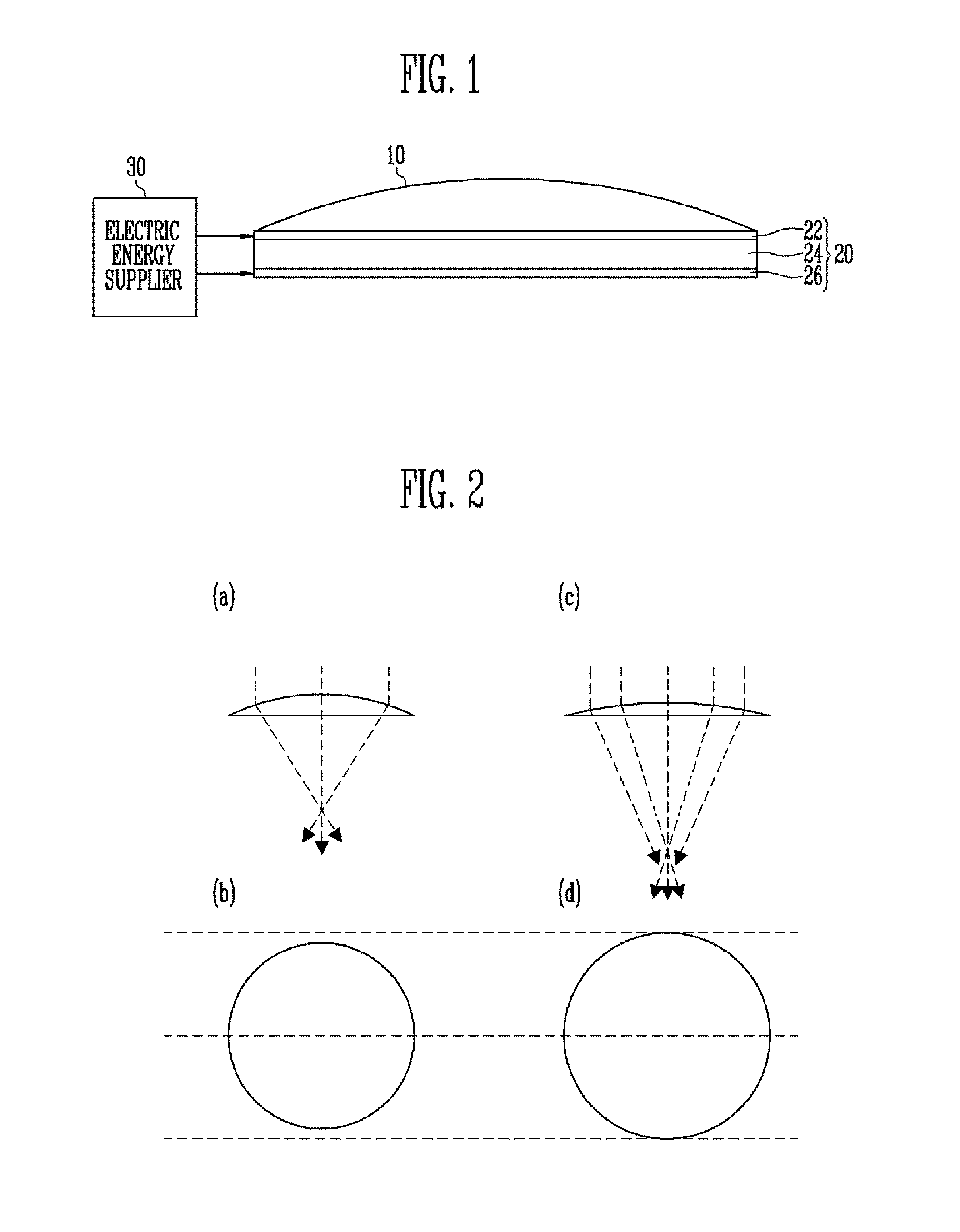
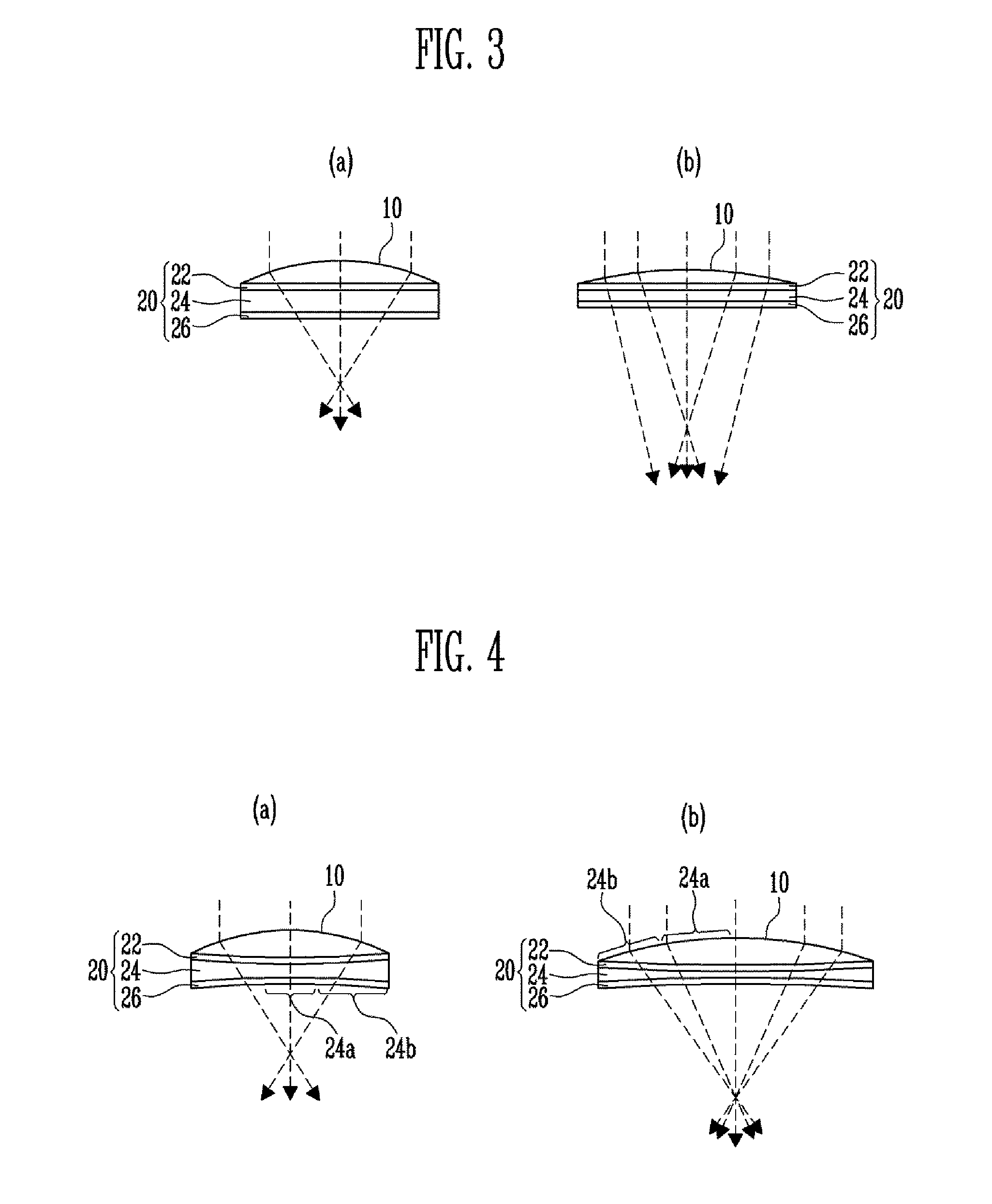
The invention provides a tunable lens system that can adjust the focal length quickly without causing spherical aberration. The system includes a transparent solid lens and a layer with electrodes that transform the shape of the lens by applying electric energy to the layer. The layer sticks to the lens and changes its shape to adjust the focal length of the lens.

Problems solved by technology

However, a conventional lens is made on the basis of glass or plastic, and thus its shape cannot be transformed, which is a problem.
However, in such a lens system, the long length of the scope tube increases the total volume and also the weight, and thus it is impossible to efficiently adjust the focus distance of the lens in a limited space, which is a problem.
However, when using the aforementioned conventional tunable lens system, if the surface of the tunable lens is torn, the liquid inside the tunable lens may leak, and the leaked liquid may cause corrosion or short circuit to the electric circuits near the tunable lens, or even affect human bodies.
Furthermore, in such the conventional tunable lens system, at least one reservoir and one injector for injecting the liquid to the chamber are always necessary near the tunable lens, thereby making it impossible to miniaturize the tunable lens system.
However, this type of tunable lens system requires some spaces around the lens.
Therefore, it is not easy to miniaturize the lens system.
However, clear images may not be acquired due to various reasons, for example, spherical aberration.
As a result, spherical aberration leads to overlapping or partially blurred images of a single object.
However, none of the conventional tunable lens systems consider spherical aberration.
This problem can result in the blur effect of an image, which is called a spherical aberration in professional terminology.

Method used


Image

  • Tunable lens system
  • Tunable lens system
  • Tunable lens system

Examples


Embodiment Construction

[0041]Hereinafter, embodiments will be described in greater detail with reference to the accompanying drawings. Embodiments are described herein with reference to cross-sectional illustrates that are schematic illustrations of embodiments (and intermediate structures). As such, variations from the shapes of the illustrations as a result, for example, of manufacturing techniques and / or tolerances, are to be expected. Thus, embodiments should not be construed as limited to the particular shapes of regions illustrated herein but may include deviations in shapes that result, for example, from manufacturing. In the drawings, lengths and sizes of layers and regions may be exaggerated for clarity. Like reference numerals in the drawings denote like elements.

[0042]Terms such as ‘first’, ‘second’, A, and B may be used to describe various components, but they should not limit the various components. Those terms are only used for the purpose of differentiating a component from other components...


PUM

PropertyMeasurementUnit
electric energyaaaaaaaaaa
areaaaaaaaaaaa
electro-viscoelasticaaaaaaaaaa

Abstract

Provided herein a tunable lens system including a lens having a transparent solid material; and a lens focus adjuster disposed below the lens, and configured such that its area contracts or expands based on the electric energy applied and transforms the shape of the lens correspondingly to the contracted or expanded area so as to adjust the focus of the lens.

Description

CROSS-REFERENCE TO RELATED APPLICATIONS[0001]The present application claims priority to Korean patent application numbers 10-2014-0006720, filed on Jan. 20, 2014 and 10-2014-0067807, filed on Jun. 3, 2014, the entire disclosure of which is incorporated herein in its entirety by reference.BACKGROUND[0002]1. Field of Invention[0003]Various embodiments of the present invention relate to a lens system, and more particularly, to a tunable lens system.[0004]2. Description of Related Art[0005]A lens is a tool for gathering or dispersing light. It may expand or reduce an image using the linear and refractive characteristics of light. However, a conventional lens is made on the basis of glass or plastic, and thus its shape cannot be transformed, which is a problem.[0006]Therefore, in a lens system having the aforementioned lens, a scope tube is provided so that one or a plurality of lens can be moved in the axial direction to adjust the focal length of the lens. However, in such a lens syste...

Claims


Application Information

Patent Timeline
Patent Type & Authority Applications(United States)
IPC IPC(8): G02B26/08G02B1/04
CPCG02B1/041G02B26/0875G02B3/14
Inventor NAM, SAE KWANGKYUNG, KI UKYUN, SUNG RYULPARK, BONG JEPARK, SUN TAK
Owner ELECTRONICS & TELECOMM RES INST
Learn More