Driver device and driving method for driving a load, in particular a light unit

a technology of driving device and load, which is applied in the direction of efficient power electronics conversion, electric lighting sources, and electric light sources, can solve the problem that the driving device known from the prior art cannot provide and achieve the effect of continuous stable power to the load

Active Publication Date: 2015-07-23
KONINKLIJKE PHILIPS ELECTRONICS NV
View PDF5 Cites 22 Cited by
  • Summary
  • Abstract
  • Description
  • Claims
  • Application Information

AI Technical Summary

Benefits of technology

[0008]It is an object of the present invention to provide a driver device and a driving method for driving a load, in particular a light unit having one or more light emitters, providing compatibility to mains ha

Problems solved by technology

Some of the standards are optional, but others are mandatory, because otherwise the product (light source including the driver) may not be released to the market in a certain region.
The limitation of the drivers known from the prior art is that the power delivered to the LED load matches the requirement as long

Method used


Image

  • Driver device and driving method for driving a load, in particular a light unit
  • Driver device and driving method for driving a load, in particular a light unit
  • Driver device and driving method for driving a load, in particular a light unit

Examples


Embodiment Construction

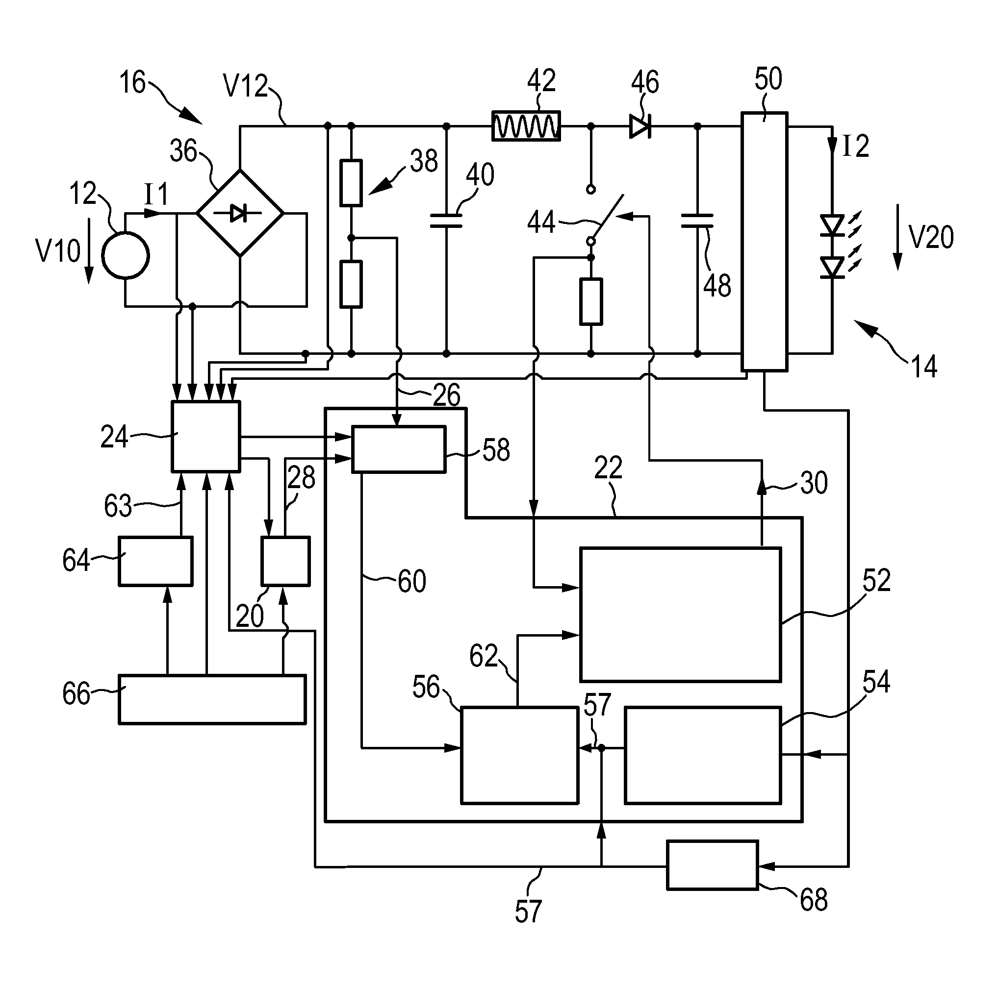
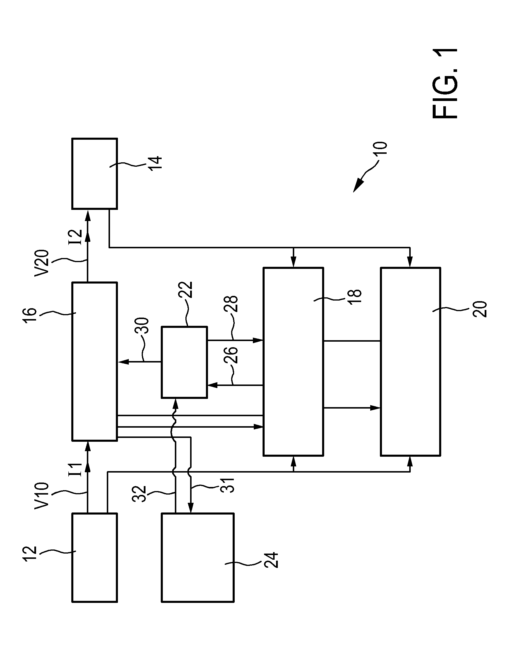
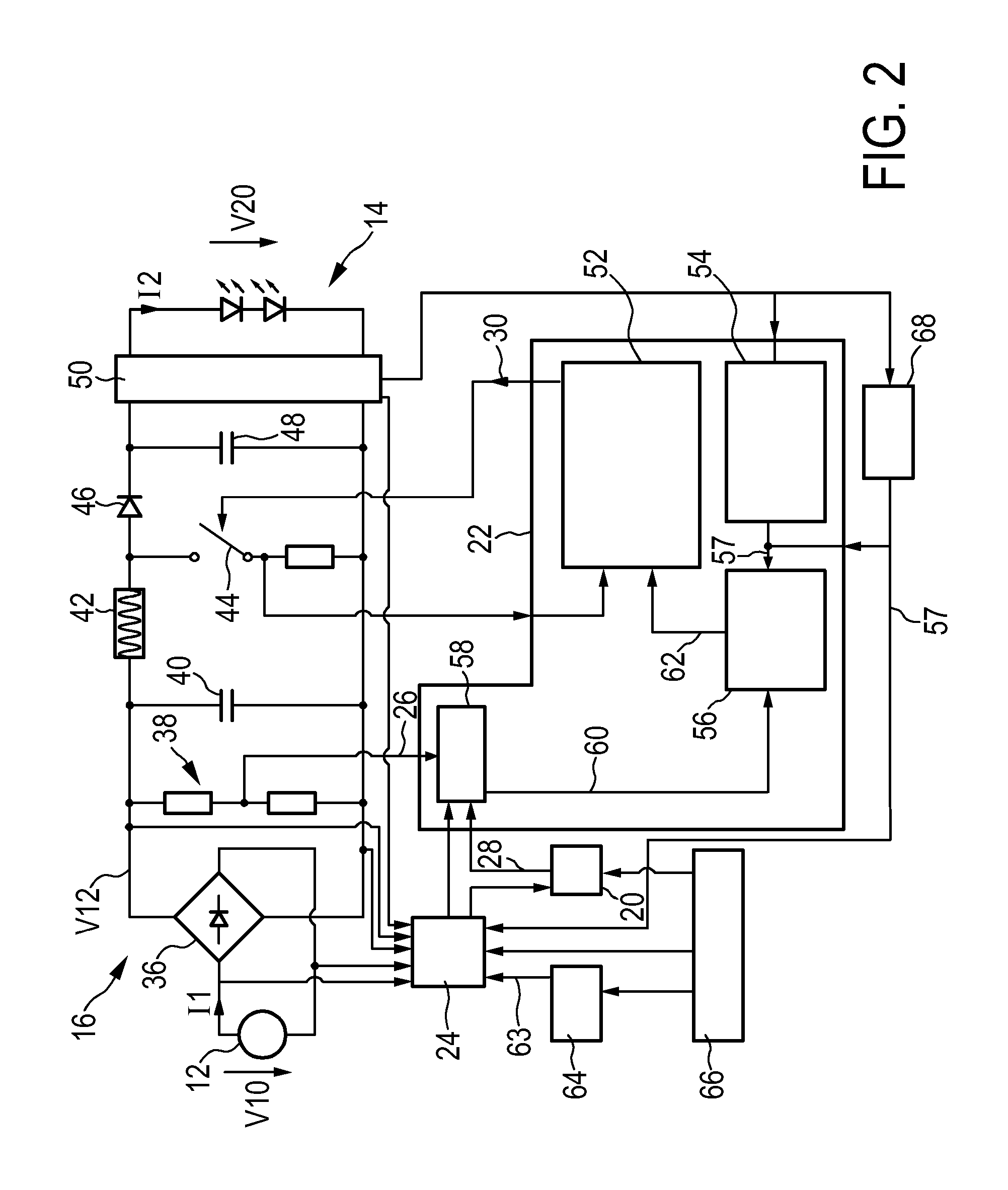
[0043]FIG. 1 shows a schematic block diagram of a driver device generally denoted 10. The driver device 10 is connected to an external voltage supply 12, which is preferably the mains, and which provides a supply voltage V10 as an input voltage V10 to the driver device 10. The driver device 10 draws an input current I1 from the external voltage supply 12. The driver device 10 provides an output voltage V20 and an output current I2 to a load 14 for powering the load 14.

[0044]The driver device 10 comprises a driver stage 16 for converting the input voltage V10 to the output voltage V20 and for drawing the input current I1 and for providing the output current I2 for powering the load. The driver device 10 further comprises a normal control loop 18 and a backup control loop 20 each connected to the external voltage supply 12, to the load 14 and to the driver stage 16 for receiving input signals. The normal control loop 18 and the backup control loop 20 are connected to a control stage 2...


PUM


Abstract

The present invention relates to a driver device (10) for driving a load (14), in particular a light unit (14) having one or more light emitters, comprising input terminals for receiving an input voltage (V10) from an external power source (12), output terminals for providing electrical power to the load for powering the load (14), a driver stage (16) connected to the input terminals and to the output terminals, wherein the driver stage (16) is adapted to control an input current (I1) drawn from the external power supply (I2) and to control the electrical power provided to the output terminal shaving a predefined level, a detection device (24) for measuring at least one electrical parameter (V10, V12, I2, V20) of the driver stage (16) and for determining an input voltage deviation from predefined supply conditions on the basis of the electrical parameter (V10, V12, I2, V20), wherein the driver stage (16) is adapted to control the input current (I1) according to predefined conditions if the input voltage deviation is lower than a threshold level (63) and to allow a deviation of the input current (I1) from the predefined conditions if the input voltage deviation exceeds the threshold level (63).

Description

FIELD OF THE INVENTION[0001]The present invention relates to a driver device and a corresponding driving method for driving a load, in particular a light unit having one or more light emitters. Further, the present invention relates to a light apparatus.BACKGROUND OF THE INVENTION[0002]Drivers for solid state light applications e.g. LED modules or retrofit lamps have to comply with mains harmonics regulations which may be defined by national or international standards, energy labels, the mains power provider, etc. Some of the standards are optional, but others are mandatory, because otherwise the product (light source including the driver) may not be released to the market in a certain region. Different kinds of power factor correction techniques are used to limit harmonics of the input current and to reduce the idle current drawn from the mains. In the optimal case, a sinusoidal input current is drawn from the mains, providing a sinusoidal supply voltage. This results in a high pow...

Claims


Application Information

Patent Timeline
IPC IPC(8): H05B33/08H05B37/02H05B44/00
CPCH05B33/0851H05B37/0227H02M1/4225H05B45/14H05B45/37Y02B70/10H05B45/10H05B47/14H05B45/00H02M1/0022H05B33/00H05B44/00
Inventor RADERMACHER, HARALD JOSEF GÜNTHERDEIXLER, PETERDEURENBERG, PETER HUBERTUS FRANCISCUS
Owner KONINKLIJKE PHILIPS ELECTRONICS NV
Why Eureka
Try Eureka