Neurofeedback system

Active Publication Date: 2015-08-06
KONINKLJIJKE PHILIPS NV
View PDF7 Cites 8 Cited by
  • Summary
  • Abstract
  • Description
  • Claims
  • Application Information

AI Technical Summary

Benefits of technology

[0028]In a further embodiment of the neurofeedback system according to the present invention, the neurofeedback system comprises a plurality of electrodes wherein a biofeedback signal is measured for each of the electrodes, and wherein the probability of a measurement error of a signal feature is determined for each of the biofeedback signals, wherein the biofeedback signal quality is determined by combining the probabilities of a measurement error. Advantageously, the biofeedback signal quality is not only determined from a biofeedback signal of a single electrode, but from the biofeedback signals of a plurality of electrodes. Furthermore, the biofeedback signal quality can be determined from a plurality of signal features from the biofeedback signals of a plurality of electrodes. This increases the reliability and accuracy of the determined biofeedback signal quality.
[0029]In a further embodiment of the neurofeedback system according to the present invention, a refreshment of the feedback provided to the user depends on the biofeedback signal quality. Feedback about the biofeedback signal quality can be provided to the user either explicitly or implicitly. In explicit feedback, the feedback about the biofeedback signal quality is decoupled from the neurofeedback mechanism. For example, information about a biofeedback signal drift can be rendered as a red traffic light that signals the user that he should not follow the neurofeedback if the light is red. Si

Problems solved by technology

The main challenge when applying EEG wet or gel electrodes is to get a good, thus low, contact impedance to the skin.
For a lifestyle consumer product as well as for disabled patients and remote monitoring purposes in clinical applications, it is not practical to use this kind of “wet” electrodes.
A problem arises when this type of electrodes has to cope with thick and long hair.
In practice, the solutions often result in poor contact to the skin at the scalp and i

Method used


Image

  • Neurofeedback system
  • Neurofeedback system
  • Neurofeedback system

Examples


Example

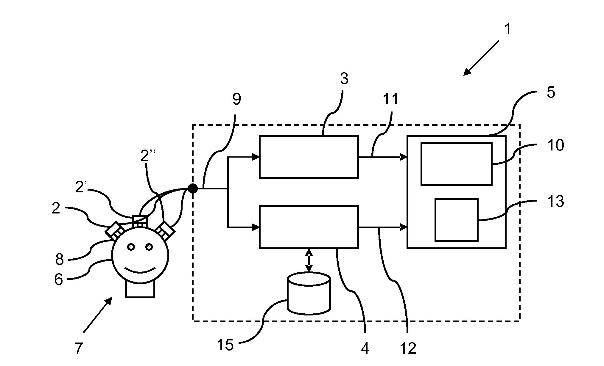
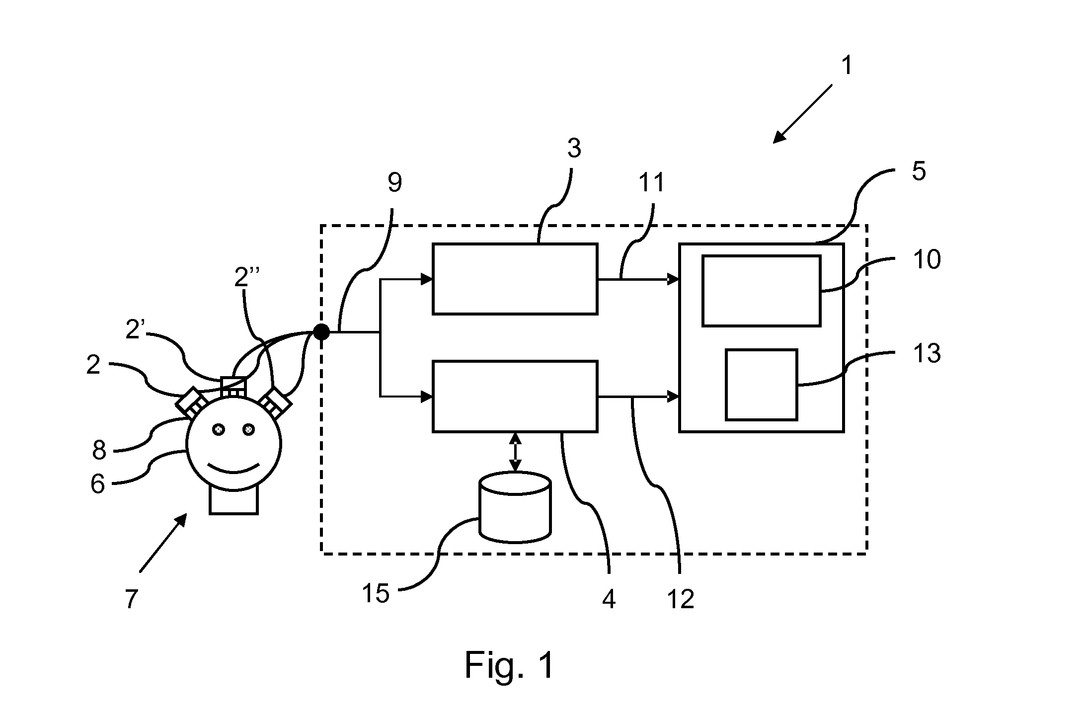
[0047]FIG. 1 shows a block diagram of a neuro feedback system 1 according to the present invention. The neurofeedback system 1 comprises an electrode 2, a first signal processing unit 3, a second signal processing unit 4 and a feedback unit 5. Optionally, the neurofeedback system 1 comprises further electrodes 2′, 2″ and a memory 15.

[0048]The electrodes 2, 2′, 2″ in this embodiment are dry electrodes that contact the skin 6, in particular the scalp, of the user 7 via pin-like contact structures 8. The electrodes 2, 2′, 2″ are used to measure a biofeedback signal 9 of the user 7. For the following explanation an EEG signal will be used as non-limiting example.

[0049]The first signal processing unit 3 is adapted to determine a signal characteristic 11 of the measured EEG signal 9. The signal characteristic 11 in the present example is alpha brain wave activity or, in other words, the spectral power of the measured EEG signal 9 in the alpha frequency domain from 8 to 12 Hz. Alternativel...


PUM


Abstract

The present invention relates to a neurofeedback system that comprises an electrode (2, 2′, 2″) for contacting skin (6) of a user (7) for measuring a biofeedback signal (9) of the user (7), a first signal processing unit (3) for determining a signal characteristic (11) of the measured biofeedback signal (9), wherein the signal characteristic (11) represents a neurofeedback, a second signal processing unit (4) for determining a biofeedback signal quality (12) of the measured biofeedback signal (9) by extracting a signal feature of the measured biofeedback signal (9) and calculating a probability of a measurement error for said signal feature, which probability represents the biofeedback signal quality (12), and a feedback unit (5) for providing feedback to the user, wherein the feedback comprises the neurofeedback and a feedback about the biofeedback signal quality (12). A further aspect of the invention relates to a method for supporting a behavior change of a person and a computer program for carrying out said method.

Description

FIELD OF THE INVENTION[0001]The present invention relates to a neurofeedback system and method to provide neuro feedback to a user. The present invention relates particularly to the field of measuring electrical brain activity, also known as electroencephalography (EEG).BACKGROUND OF THE INVENTION[0002]Electrical brain activity or EEG is measured by means of EEG electrodes contacting the skin of a user, in particular the scalp of the user. One type of known electrodes are wet or gel electrodes. Another type of known electrodes are dry electrodes (not using gel). The main challenge when applying EEG wet or gel electrodes is to get a good, thus low, contact impedance to the skin. In clinical measurements this is normally done with a (shower-cap like) rubber cap with integrated metal electrodes (e.g. Ag / AgCl coated). The skin underneath these electrodes usually needs to be prepared by degreasing and often additional abrasion (e.g. removal of the dry top layer of the skin, the stratum c...

Claims


Application Information

Patent Timeline
IPC IPC(8): A61B5/0482A61B5/00A61B5/04A61B5/296A61B5/375
CPCA61B5/04012A61B5/0482A61B5/7221A61B5/375A61B5/316A61B5/374
Inventor MIHAJLOVIC, VOJKAN
Owner KONINKLJIJKE PHILIPS NV
Why Eureka
Try Eureka