Output driver

Active Publication Date: 2009-12-10
SK HYNIX INC
View PDF14 Cites 2 Cited by
  • Summary
  • Abstract
  • Description
  • Claims
  • Application Information

AI Technical Summary

Benefits of technology

[0026]Recently, the various methods are applied to the output driver in order to control the slew rate of the pull-up and pull-down driving control signals. However, the limitation in increasing a chip area has been accompanied with these applications. In particular, as operation speed of the recent semiconductor memory device gets higher, the pull-up and pull-down driving control signals may not make a full swing. The existing output driver having such a shortcoming appears very weak in power noises or PVT conditions. Because an output terminal is additionally driven in accordance with the data input into the output driver, it is possible to control the slew rate of

Problems solved by technology

However, because a switch used in a metal option mask occupies a relatively large area, there is a limitation in increasing the number of the switches.
As described above, when the pull-up driving control signal CTR_PU and the pull-down driving control signal CTR_PD do not achieve a target slew rate, data output from the output terminal OUT also may accordingly hav

Method used


Image

  • Output driver
  • Output driver
  • Output driver

Examples


Embodiment Construction

[0034]Hereinafter, an output driver in accordance with an embodiment of the present invention will be described in detail with reference to the accompanying drawings.

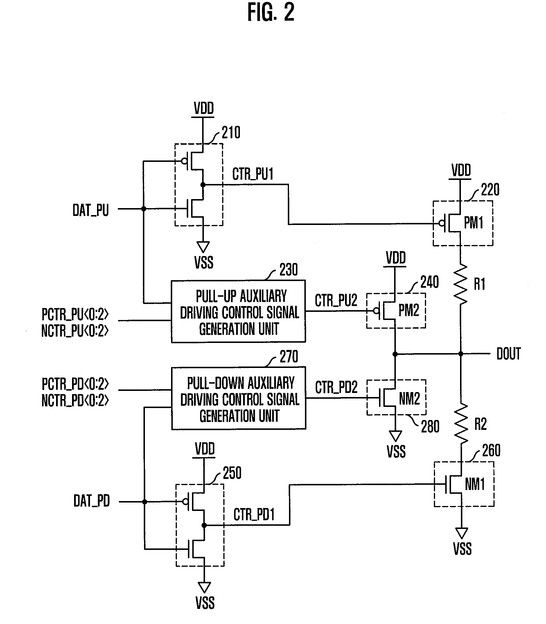
[0035]FIG. 2 is a circuit diagram illustrating an output driver in accordance with an embodiment of the present invention.

[0036]Referring to FIG. 2, the output driver includes a pull-up pre-driving unit 210, a pull-up main driving unit 220, a pull-up auxiliary driving control signal generation unit 230, a pull-up auxiliary driving unit 240, a pull-down pre-driving unit 250, a pull-down main driving unit 260, a pull-down auxiliary driving control signal generation unit 270, and a pull-down auxiliary driving unit 280.

[0037]The pull-up pre-driving unit 210 generates a pull-up main driving control signal CTR_PU1 in response to a pull-up data signal DAT_PU, and includes a PMOS transistor and an NMOS transistor, which are series-connected between an external voltage terminal VDD and a ground voltage terminal VSS and each rece...


PUM


Abstract

There is provided an output driver, which includes a pre-driver configured to generate a main driving control signal in response to a data signal, a main driver configured to drive an output terminal in response to the main driving control signal, an auxiliary driving control signal generator configured to generate an auxiliary driving control signal having an activation interval corresponding to the data signal and an interval control signal, and an auxiliary driver configured to drive the output terminal in response to the auxiliary driving control signal.

Description

CROSS-REFERENCE TO RELATED APPLICATION[0001]This application claims priority of Korean patent application number 2008-0052744, filed on Jun. 4, 2008, which is incorporated by reference in its entirety.BACKGROUND OF THE INVENTION[0002]The subject matter relates to a semiconductor design, and more particularly, to an output driver capable of ensuring the integrity of output data by controlling a slew rate of the output data.[0003]Generally, a semiconductor memory device including double data rate synchronous DRAM (DDR SDRAM) outputs data to the outside using an internal clock signal synchronized with an external clock signal. In the semiconductor memory device, the data is synchronized with a rising edge and a falling edge of the external clock signal. Accordingly, an output driver is required in the semiconductor memory device in order to receive the internal clock signal and output data corresponding to the external clock signal.[0004]FIG. 1 is a circuit diagram illustrating a conve...

Claims


Application Information

Patent Timeline
IPC IPC(8): H03K19/0175
CPCH03K19/018528G11C7/1051G11C11/4072G11C11/4076G11C11/4093G11C11/4096H03K19/018521
Inventor KIM, KYUNG-HOONKWON, DAE-HANSONG, TAEK-SANG
Owner SK HYNIX INC
Why Eureka
Try Eureka