Transcatheter mitral valve prosthesis

a transcatheter mitral valve and prosthesis technology, applied in the field of medical devices and methods, can solve the problems of not being indicated for all patients, difficult to deliver, and expensive to manufacture, and achieve the effect of limiting the proximal retraction of the sheath and preventing retrograde blood flow therepas

Active Publication Date: 2015-08-06
EDWARDS LIFESCI CARDIAQ +1
View PDF3 Cites 76 Cited by
  • Summary
  • Abstract
  • Description
  • Claims
  • Application Information

AI Technical Summary

Benefits of technology

[0048]The system may further comprise the prosthetic cardiac valve which may be housed in the sheath in a radially collapsed configuration. The prosthetic cardiac valve may comprise an anchor having an atrial skirt, an annular region, and a ventricular skirt. The prosthetic valve may also comprise a plurality of prosthetic valve leaflets. Each of the leaflets may have a first end and a free end. The first end may be coupled with the anchor and the free end may be opposite of the first end. The prosthetic cardiac valve may have an open configuration in which the free ends of the prosthetic valve leaflets are disposed away from one another to allow antegrade bloodflow therepast. The valve may have a closed configuration in which the free ends of the prosthetic valve leaflets engage one another and substantially prevent retrograde blood flow therepast.
[0049]Proximal retraction of the sheath relative to the bell shaft may remove a constraint from the prosthetic cardiac valve thereby allowing the prosthetic cardiac valve to self-expand into engagement with the patient's native heart tissue. The prosthetic cardiac valve may be releasably coupled with the hub shaft, and proximal retraction of the bell shaft relative to the hub shaft may release the prosthetic cardiac valve therefrom. The actuator mechanism may comprise a rotatable wheel. The system may further comprise a tissue penetrating distal tip coupled to the hub shaft. The tissue penetrating distal tip may be adapted to pass through and expand an incision in the patient's heart. The system may further comprise a pin lock mechanism releasably coupled with the handle. The pin lock mechanism may limit proximal retraction of the sheath.

Problems solved by technology

While these devices and methods are promising treatments for valvar insufficiency, they can be difficult to deliver, expensive to manufacture, or may not be indicated for all patients.

Method used


Image

  • Transcatheter mitral valve prosthesis
  • Transcatheter mitral valve prosthesis
  • Transcatheter mitral valve prosthesis

Examples


Embodiment Construction

[0081]Specific embodiments of the disclosed device, delivery system, and method will now be described with reference to the drawings. Nothing in this detailed description is intended to imply that any particular component, feature, or step is essential to the invention.

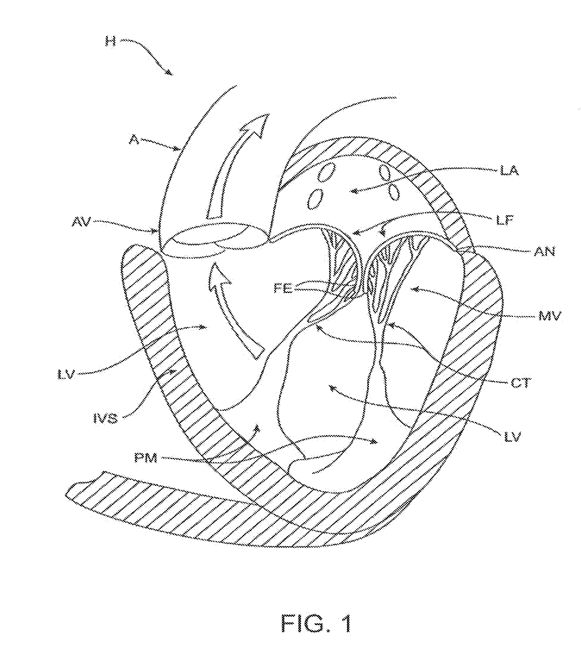
[0082]Cardiac Anatomy. The left ventricle LV of a normal heart H in systole is illustrated in FIG. 1. The left ventricle LV is contracting and blood flows outwardly through the aortic valve AV, a tricuspid valve in the direction of the arrows. Back flow of blood or “regurgitation” through the mitral valve MV is prevented since the mitral valve is configured as a “check valve” which prevents back flow when pressure in the left ventricle is higher than that in the left atrium LA. The mitral valve MV comprises a pair of leaflets having free edges FE which meet evenly to close, as illustrated in FIG. 1. The opposite ends of the leaflets LF are attached to the surrounding heart structure along an annular region referred to...


PUM


Abstract

A prosthetic cardiac valve comprises an anchor having an atrial skirt, an annular region, and a ventricular skirt. The prosthetic valve also has a plurality of prosthetic valve leaflets each having a first end and a free end. The first end is coupled with the anchor and the free end is opposite the first end. The prosthetic cardiac valve has an open configuration in which the free ends of the prosthetic valve leaflets are disposed away from one another to allow antegrade blood flow therepast, and a closed configuration in which the free ends of the prosthetic valve leaflets engage one another and substantially prevent retrograde blood flow therepast. The anchor has a collapsed configuration for delivery to the heart and an expanded configuration for anchoring the prosthetic cardiac valve to a patient's heart.

Description

CROSS-REFERENCE TO RELATED APPLICATIONS[0001]This application is a continuation of U.S. patent application Ser. No. 14 / 046,606 (Attorney Docket No. 42194-703.401), filed Oct. 4, 2013, which is a divisional of U.S. patent application Ser. No. 13 / 096,572 (Attorney Docket No. 42194-703.201, now U.S. Pat. No. 8,579,964), filed Apr. 28, 2011, which claims the benefit of U.S. Provisional Patent Application Nos. 61 / 414,879 (Attorney Docket No. 42194-703.103) filed Nov. 17, 2010; 61 / 393,860 (Attorney Docket No. 42194-703.102) filed Oct. 15, 2010; and 61 / 331,799 (Attorney Docket No. 42194-703.101) filed May 5, 2010; the entire contents of which are incorporated herein by reference.BACKGROUND OF THE INVENTION[0002]1. Field of the Invention[0003]The present invention generally relates to medical devices and methods, and more particularly relates to the treatment of valve insufficiency, such as mitral insufficiency, also referred to as mitral regurgitation. The use of prosthetic valves delivere...

Claims


Application Information

Patent Timeline
Patent Type & Authority Applications(United States)
IPC IPC(8): A61F2/24
CPCA61F2/2418A61F2/2436A61F2002/9505A61F2002/9517A61F2/2412A61F2/2409A61F2220/0008A61F2220/0016A61F2230/005A61F2230/0054A61F2/2427A61F2250/0067A61F2250/0098A61F2230/0034A61F2/9517A61F2250/0039
Inventor LANE, RANDY MATTHEWNYULI, COLIN A.
Owner EDWARDS LIFESCI CARDIAQ
Why Eureka
Try Eureka