

Image stabilizing device and system for telescopic optical instruments
a technology of optical instruments and stabilizing devices, which is applied in the field of image stabilizing devices and systems for telescopic optical instruments, can solve the problems of affecting the resolution of telescopic optical images, affecting the operation of dynamo-electric machines, and instruments that may encounter user hand shake, etc., and achieves the effects of reducing manufacturing costs, reducing manufacturing costs, and simplifying the gimbal drive mechanism
- Summary
- Abstract
- Description
- Claims
- Application Information
AI Technical Summary
Benefits of technology
Problems solved by technology
Method used
Image

Examples
Embodiment Construction
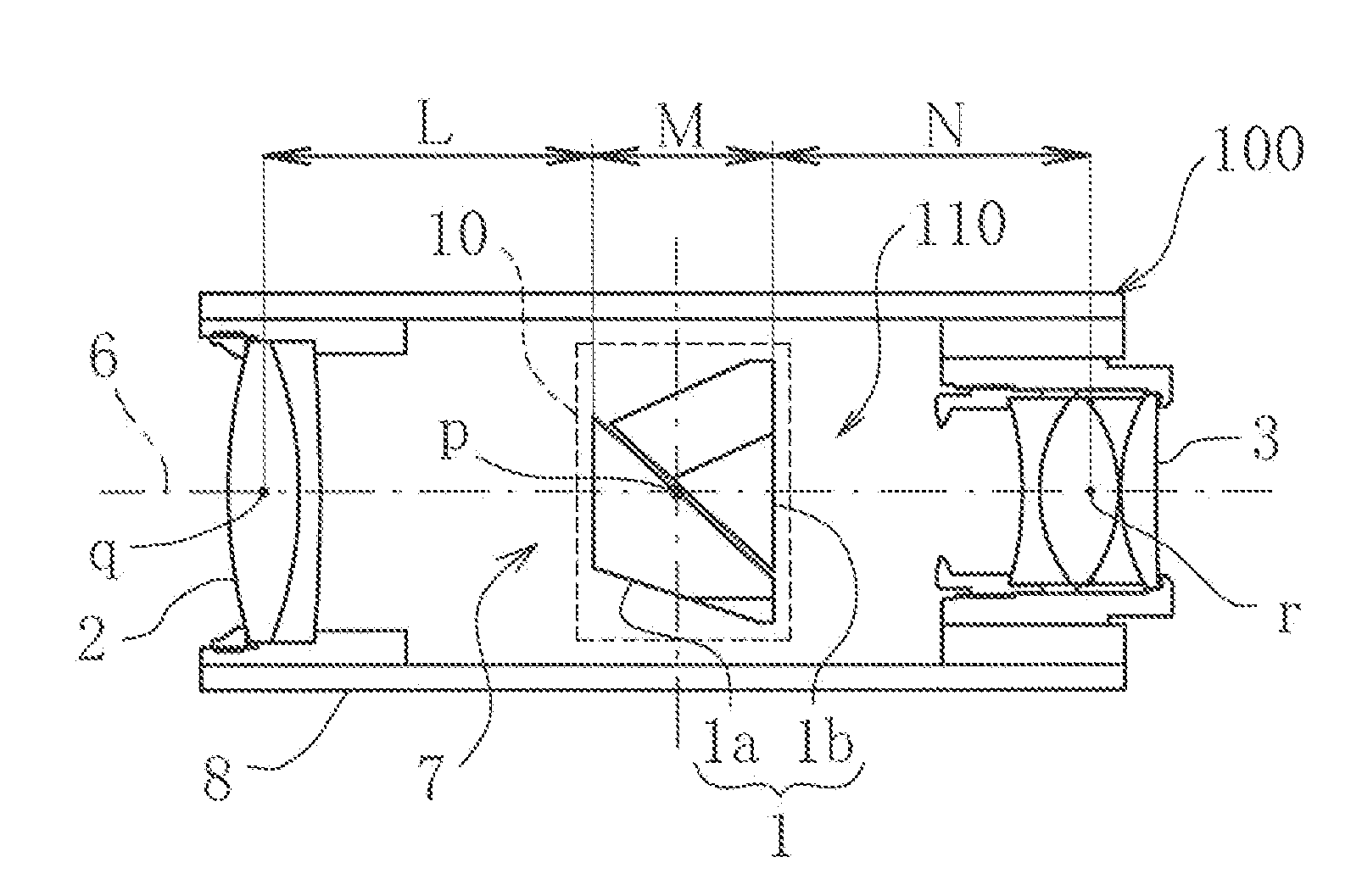
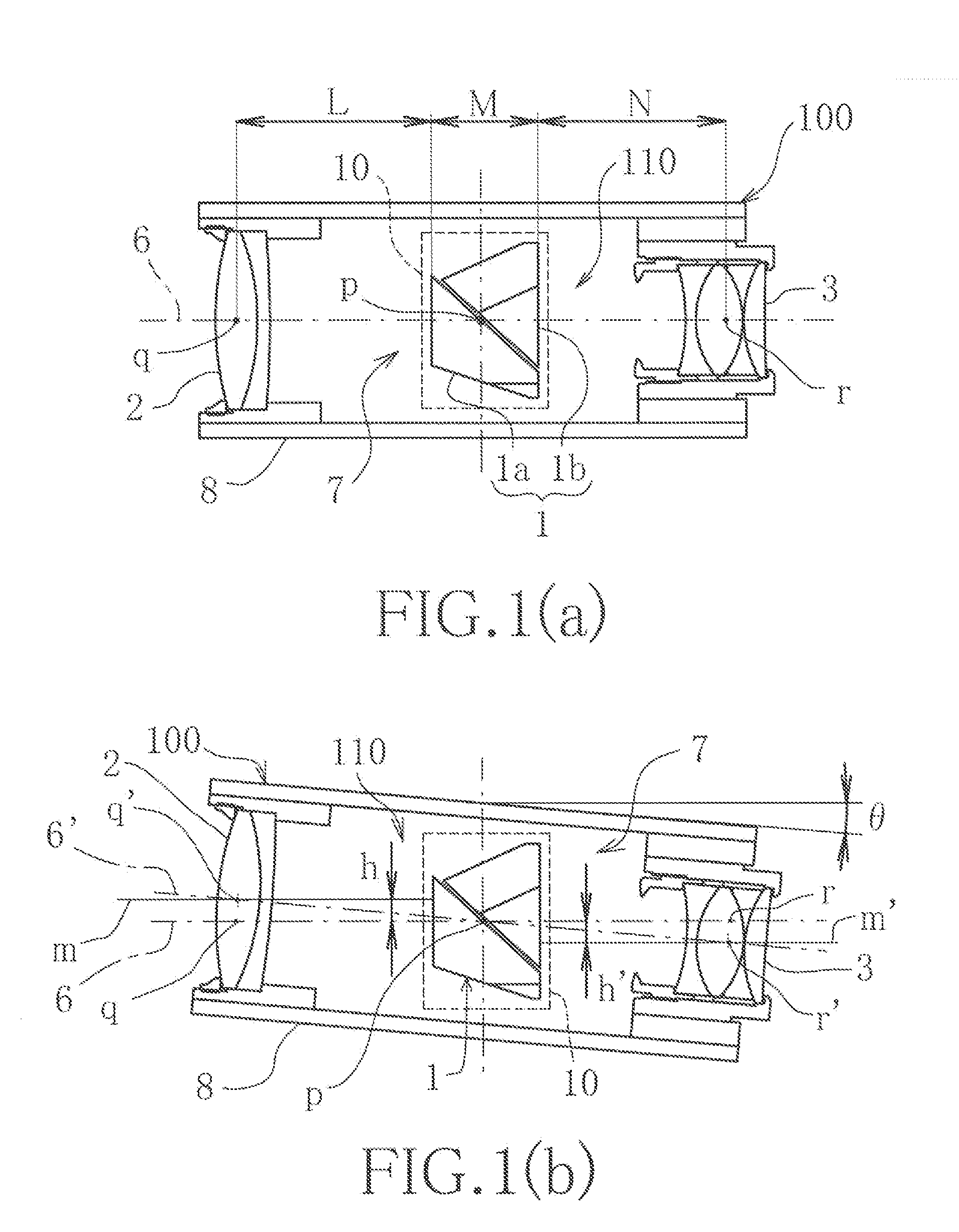
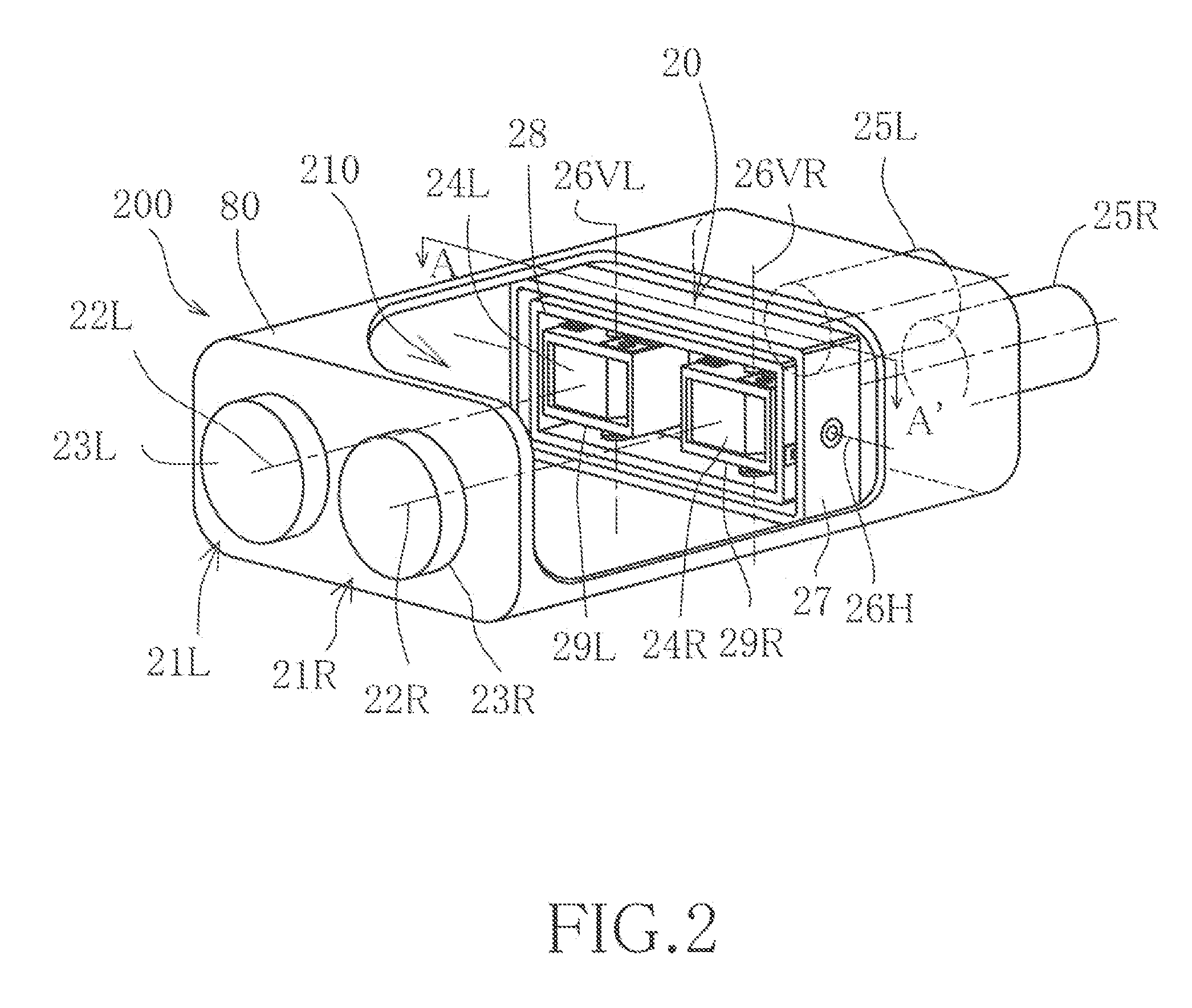
[0014]The image stabilizing device and system of the present apparatus advantageously provides an image stabilizing device for a binocular telescope which is free from the deterioration in the telescopic optical images viewed through the right and left telescopic optical systems due to the differences in visual appearance arising out of disconformities in the physical relationship among the optical components between juxtaposed telescopic optical systems when the image stabilizing device reacts to compensate for horizontal vibrations or motions.
[0015]The image stabilizing device and system of this concept also advantageously provides an image stabilizing device comprising a system to drive or actuate a gimbal device, constituting a key component of the image stabilizing device which is readily miniaturized, reduced in weight, and of relatively low cost to manufacture.
[0016]In a representative embodiment of the image stabilizing device and system disclosed herein, there is provided a...
PUM
 Abstract
Description
Claims
Application Information