Wearable computing device

a technology of wearable electronics and computing devices, applied in the direction of digital computer details, mechanical pattern conversion, electric signalling details, etc., can solve the problems of inconvenient wear of wearable electronics, inconvenient use, and inability to meet the needs of wearers, so as to prevent overheating

Active Publication Date: 2015-08-06
OURARING INC
View PDF11 Cites 193 Cited by
  • Summary
  • Abstract
  • Description
  • Claims
  • Application Information

AI Technical Summary

Benefits of technology

[0032]In one example, the lid includes a plurality of vent holes that prevent overheating within the enclosure.

Problems solved by technology

However, many current wearable electronics are bulky and can be intrusive or interfere with a person's daily life.
In this regard, the wearer may not be comfortable wearing the device for extended periods of time.

Method used


Image

  • Wearable computing device
  • Wearable computing device
  • Wearable computing device

Examples


Embodiment Construction

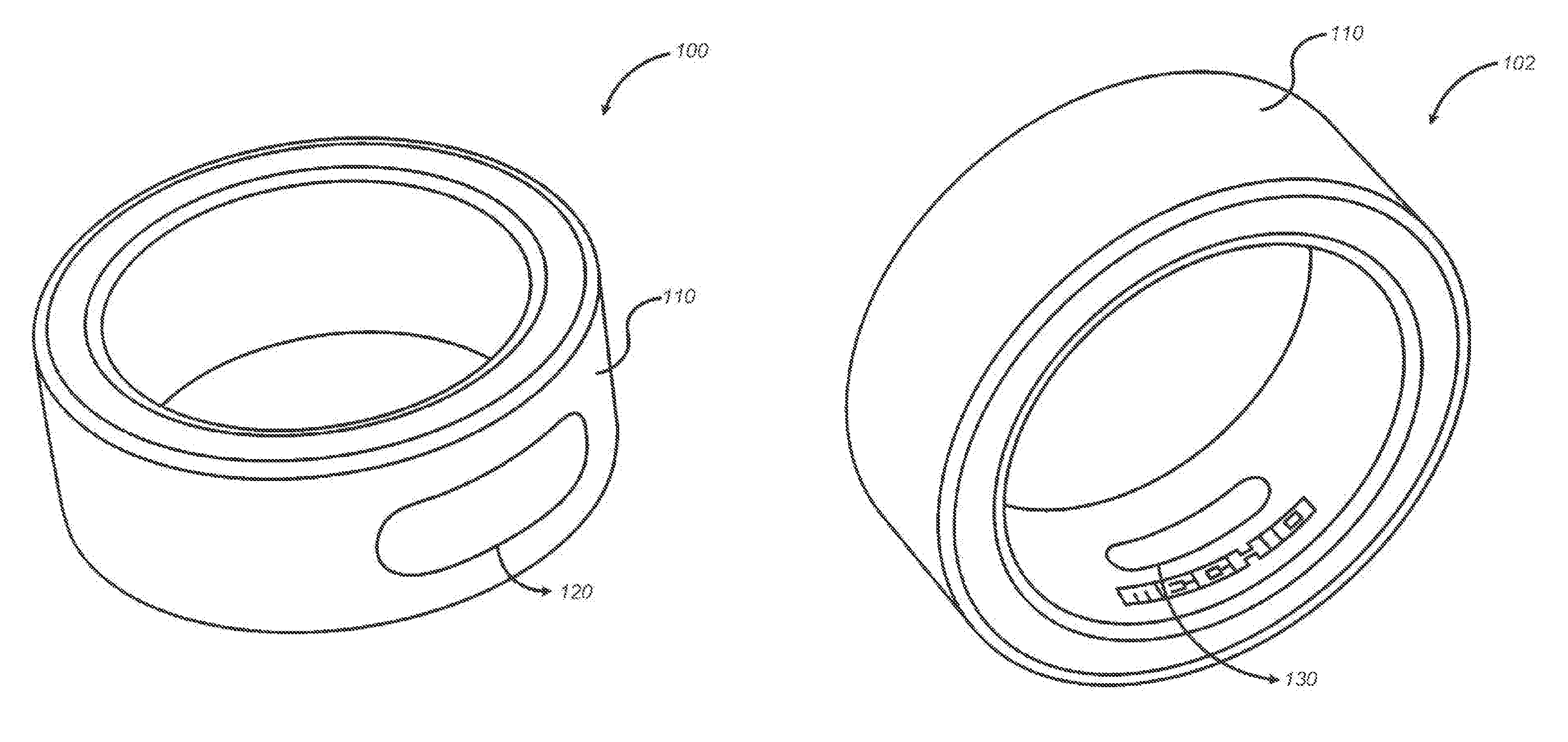
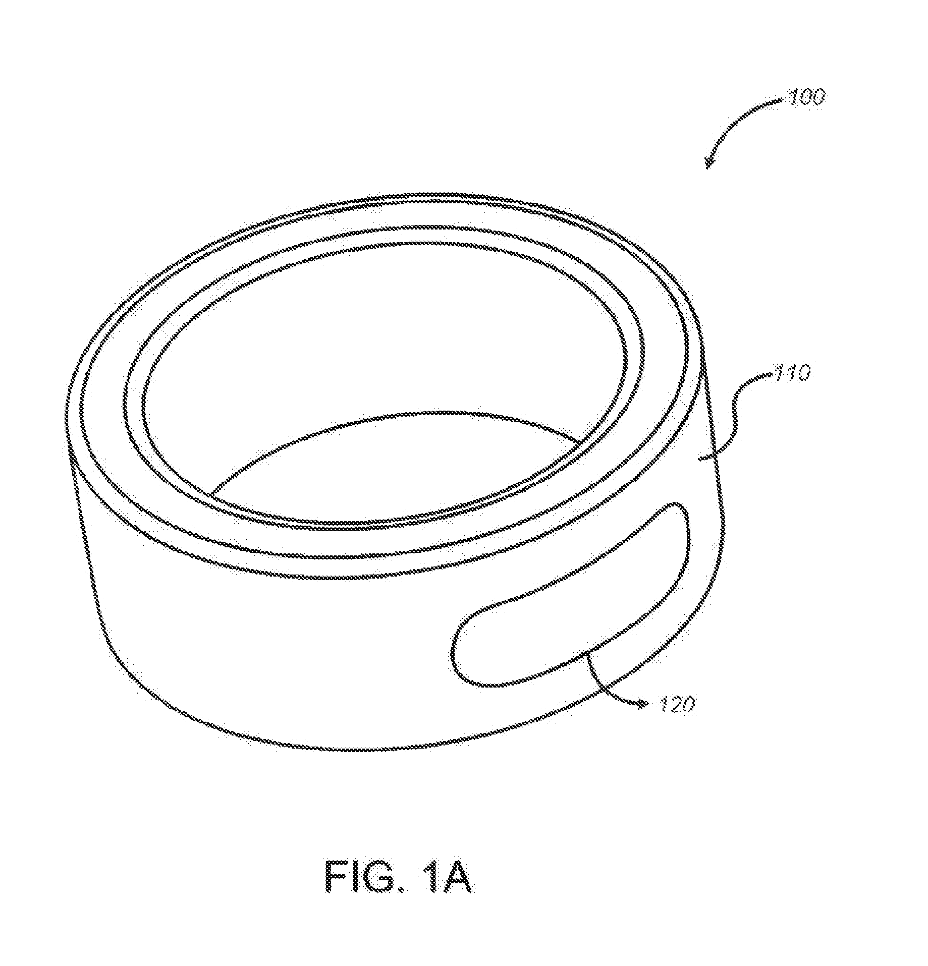
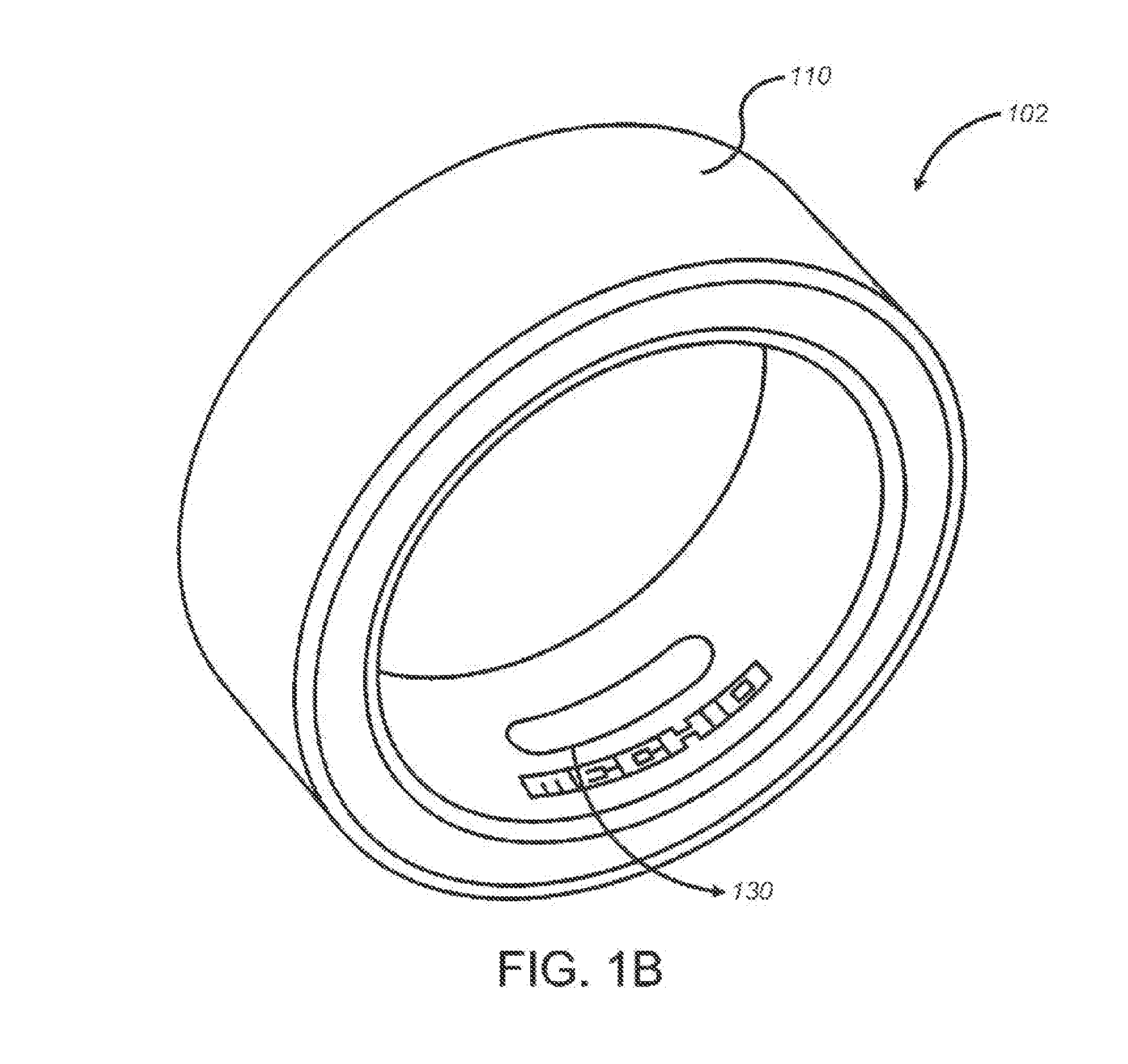
[0155]The present disclosure describes a wearable computing device (WCD) that enables a wearable fitness monitor(s) / computer(s) which is suitable for prolonged usage with accurate results. The WCD can be in the form of a ring that can be worn on the finger of a human (or animal) user. Although the WCD of the present disclosure is depicted as a ring that can be worn on the finger of a user, other shapes, designs, and form factors can be utilized for the WCD. For example, the WCD can be in the form of a wrist band, bracelet, necklace, earring, or any other type of wearable accessory. In this regard, references to the finger of a user in the present application can be considered to apply to other portions of a human body depending on the form of the WCD, such as wrist, neck, ear, etc.

[0156]The term “coupled” as used herein means connected directly to or connected through one or more intervening components or circuits. Any of the signals provided over various buses described herein may ...


PUM


Abstract

The present disclosure describes a wearable computing device (WCD) in the form of a ring that can be worn on the finger of a human user.

Description

RELATED APPLICATIONS[0001]This application claims the benefit of U.S. Provisional Application Ser. No. 62 / 006,835, filed Jun. 2, 2014, entitled WEARABLE COMPUTING DEVICE and U.S. Provisional Application Ser. No. 61 / 910,201, filed Nov. 29, 2013, entitled FINGER RING DEVICE FOR ACTIVITY MONITORING OR FESTURAL INPUT, the entire disclosures of which is herein incorporated by reference.FIELD OF THE INVENTION[0002]This invention is in the field of wearable electronic devices.BACKGROUND OF THE INVENTION[0003]Wearable electronics are an emerging technology with many applications for the wearer. They can improve lifestyles, ease access to technology and help monitor activity within the wearer's body. However, many current wearable electronics are bulky and can be intrusive or interfere with a person's daily life. In this regard, the wearer may not be comfortable wearing the device for extended periods of time.SUMMARY OF THE INVENTION[0004]This invention overcomes the disadvantages of the pri...

Claims


Application Information

Patent Timeline
Patent Type & Authority Applications(United States)
IPC IPC(8): G06F1/16G06K9/00G01P15/00G08C17/02G04G21/02G06F3/01G08B21/02A61B5/332
CPCG06F1/16G01P15/00G08B21/02G06K9/00885G08C17/02G06F3/014G06F1/163G04G21/02G06F3/017A61B5/681A61B5/6826A61B2560/0214A61B2560/0412A61B2562/146A61B2562/164A61B2562/166Y02E10/52H02J7/35A61B5/332A61B5/349G06V40/10G06V40/70G06V40/15G06V10/751G06F1/1635G06F3/14G08B5/36H02J7/0044H02S40/22G02B19/0042G02B19/0052G02B19/0061H02S99/00A61B5/01A61B5/021A61B5/02416A61B5/1118A61B5/14532A61B5/1455G06F21/32G08C2201/30A61B5/0205G04G21/025
Inventor VON BADINSKI, CURT C.STRASSER, MICHAEL J.TWISS, PETER
Owner OURARING INC
Why Eureka
Try Eureka