Braking System for Motor Vehicles and Method for the Operation of a Braking System

a technology for braking systems and motor vehicles, applied in braking systems, braking components, transportation and packaging, etc., can solve the problems of limited volume of pressure medium that can be displaced from the second chamber and moved into the pressure medium reservoir, and achieve the effect of avoiding the noise of the isolation valve, and shortening the travel of the brake pedal

Active Publication Date: 2015-08-13
CONTINENTAL TEVES AG & CO OHG
View PDF6 Cites 24 Cited by
  • Summary
  • Abstract
  • Description
  • Claims
  • Application Information

AI Technical Summary

Benefits of technology

[0027]Preferably, when a predetermined condition is present, the isolation valve is not closed during the entire braking operation when the brake pedal is actuated. In this way, switching noises from the isolation valve are avoided. It is only possible to dispense with closure of the isolation valve because the quantity of pressure medium displaced into the pressure medium reservoir is limited, even when the isolation valve is open. As a particular preference, the isolation valve is not closed when a first option has been chosen by the vehicle driver via an HMI interface. It is advantageous if the first option corresponds to a setting of the braking system (“comfort setting”) in which the force/displacement characteristic curve has a gentle slope in the case of small brake pedal travels.
[0028]When a predetermined condition is present, the isolation valve is preferably immediately closed when the brake pedal is actuated, and, as a particular preference, remains closed during the entire braking operation. In this way, pressure medium is prevented from being held in the media separating device, and the pressure medium is received by the simulation device. The brake pedal feel is thus determined by the elastic element of the simulation device. As a particular preference, the isolation valve is immediately closed when a second option has been chosen by the vehicle driver via an HMI interface. It is advantag

Problems solved by technology

However, the pressure medium volume that can be accommodated in the first chamber is limited by the media separating element and, accordin

Method used


Image

  • Braking System for Motor Vehicles and Method for the Operation of a Braking System
  • Braking System for Motor Vehicles and Method for the Operation of a Braking System
  • Braking System for Motor Vehicles and Method for the Operation of a Braking System

Examples


Embodiment Construction

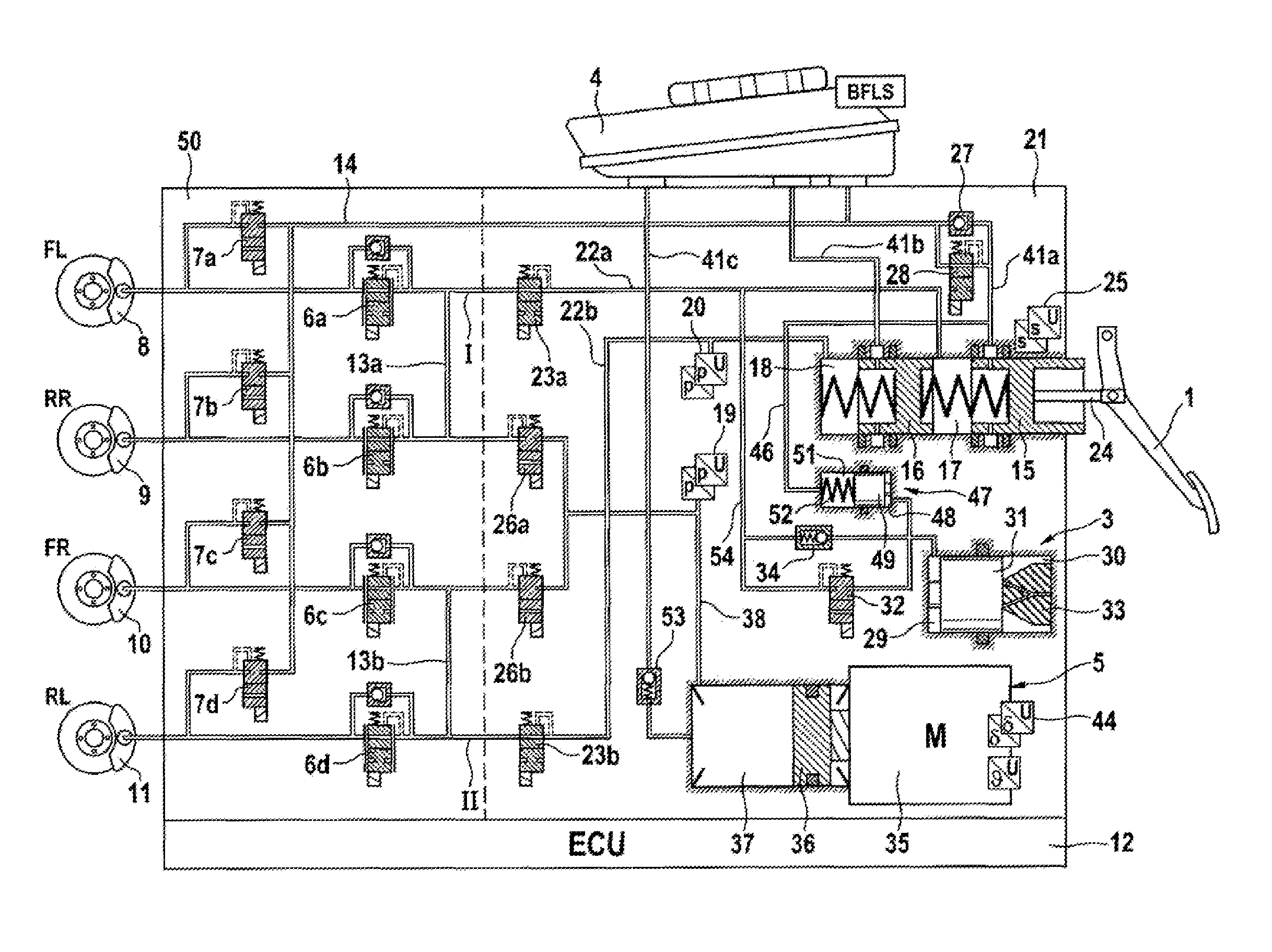
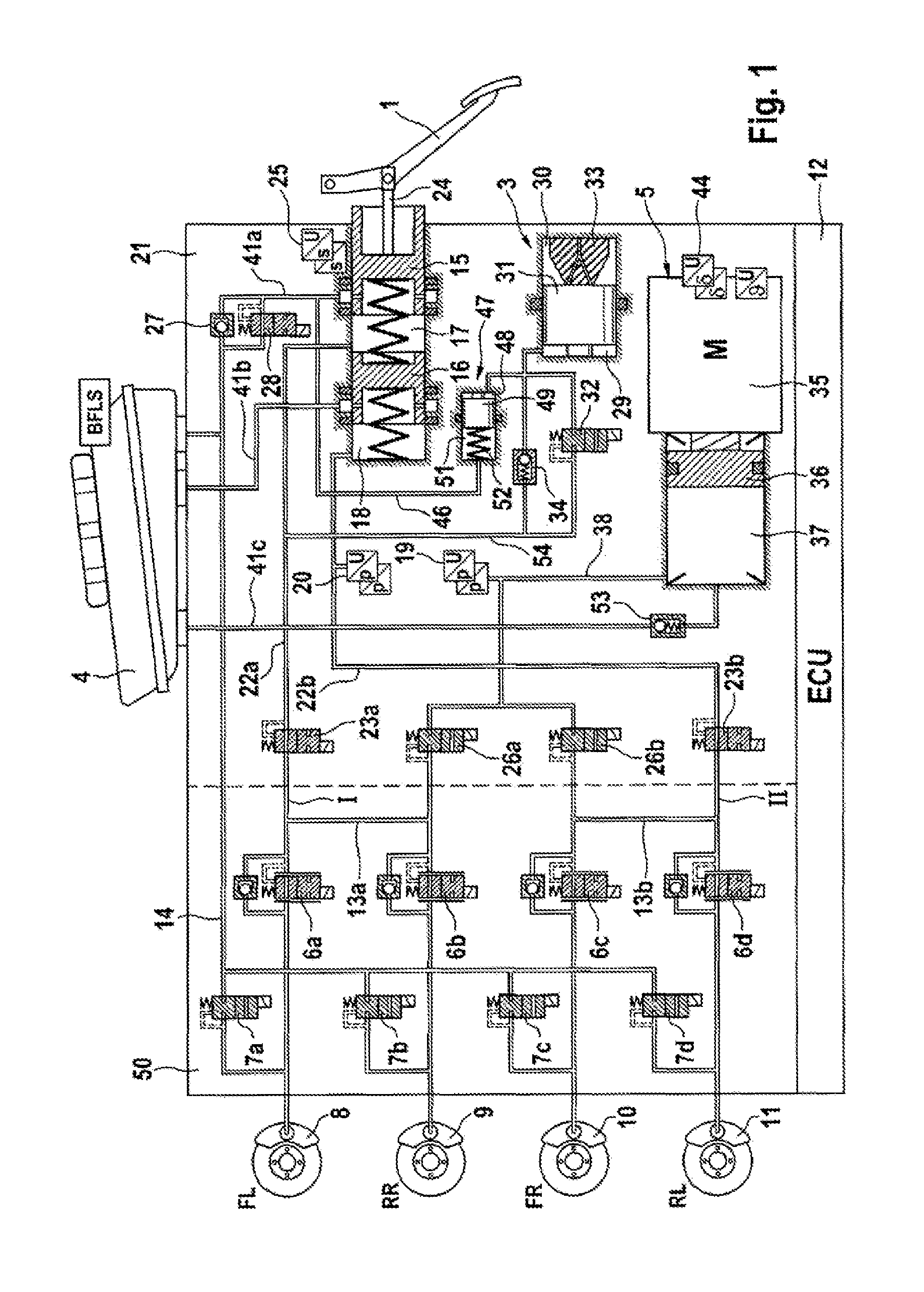
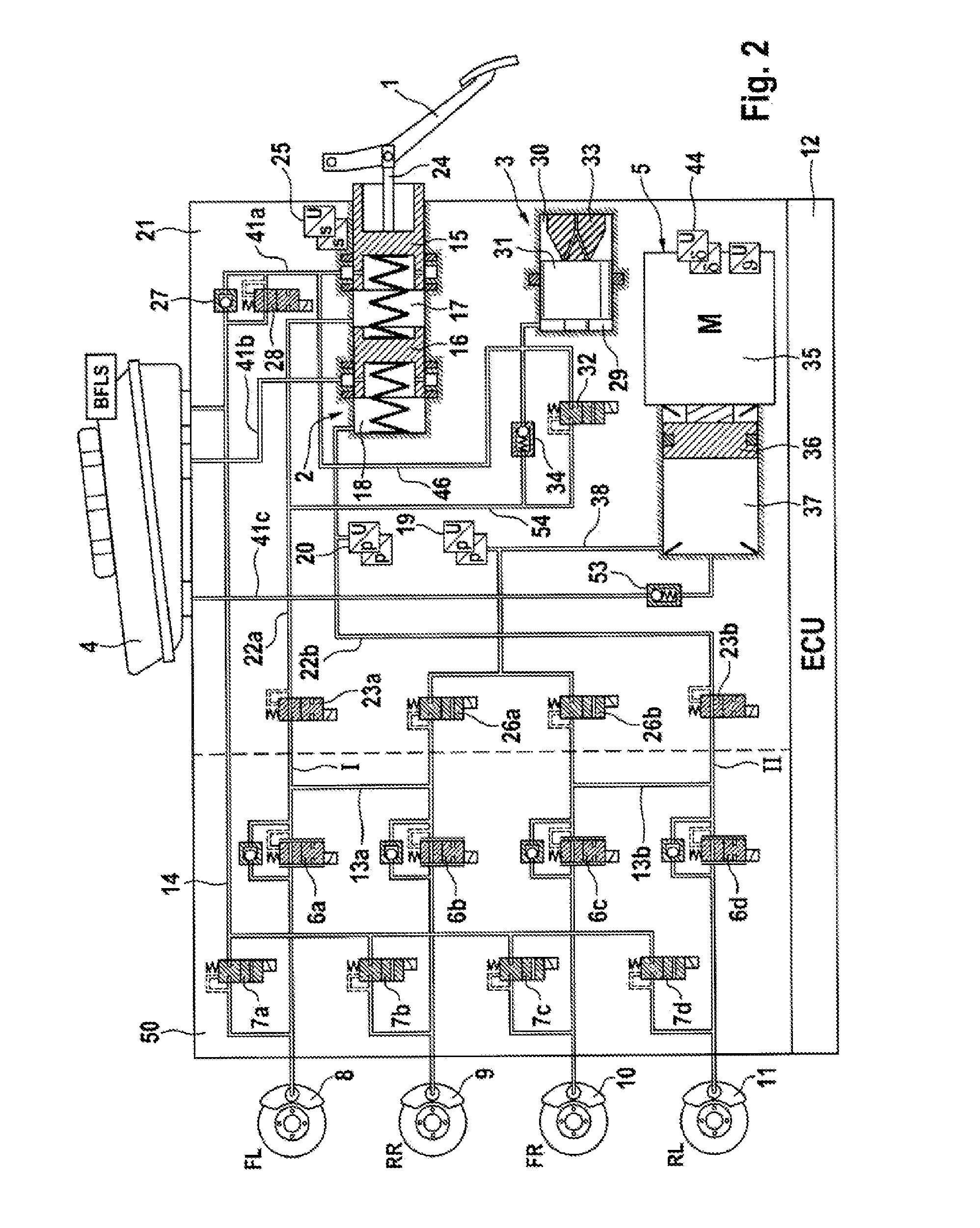
[0034]An illustrative embodiment of a braking system according to the invention is shown schematically in FIG. 1. The braking system essentially includes a hydraulic actuating unit 2, which can be actuated by means of an actuating or brake pedal 1, a travel simulator or simulation device 3, which interacts with the hydraulic actuating unit 2, a pressure medium reservoir 4, which is associated with the hydraulic actuating unit 2 and is under atmospheric pressure, an electrically controllable pressure supplying device 5, an electronic open-loop and closed-loop control unit 12 and an electrically controllable pressure modulation device 50.

[0035]According to the example, pressure modulation device 50 all-trade-to-dummy includes an inlet valve 6a-6d and an outlet valve 7a-7d for each wheel brake 8, 9, 10, 11 of a motor vehicle (not shown), said valves being hydraulically connected in pairs, via center ports, to one another and to the wheel brakes 8, 9, 10, 11. The inlet ports of the inle...


PUM


Abstract

A motor vehicle braking system and method operable in a brake-by-wire mode and independently of the driver, with a master brake cylinder (2) operated by a brake pedal (1) having a piston (15, 16) and a pressure chamber (17, 18), connected with a brake circuit (I, II) and wheel brakes (8,9, 10, 11). An electrically controllable pressure supplying device (5) operates the wheel brakes; and a simulation device (3) with at least one elastic element (33), provides an acceptable brake pedal feel in the brake-by-wire mode. The simulation device (3) has a simulator chamber (29) connected, or is hydraulically connected, through a first hydraulic connection (54) to the pressure chamber (17) and which has an electrically actuated isolation valve (28) with a pressure means reservoir (4) under atmospheric pressure. A media separator device (47) is arranged in the connection (46) between the simulator chamber (29) and the isolation valve (28).

Description

CROSS REFERENCE TO RELATED APPLICATIONS[0001]This application claims priority to German Patent Application No. 10 2012 215 627.5, filed on Sep. 4, 2012; and PCT / EP2013 / 064689, filed Jul. 11, 2013.FIELD OF THE INVENTION[0002]The invention relates to a braking system for motor vehicles to a method for the operation of a braking systemBACKGROUND[0003]Hydraulic vehicle braking systems which are designed as power-operated braking systems and, in addition to a muscle-powered brake master cylinder, to which wheel brakes are hydraulically connected and which supplies pressure and volume for the actuation of wheel brakes, may include a further, electrically controllable pressure and volume supplying device, which controls the wheel brakes in a “brake by wire” operating mode, are known. In such a system, if the electrically controllable pressure and volume supplying device fails, the wheel brakes are actuated exclusively by the muscle power of the vehicle driver (unassisted fallback operating...

Claims


Application Information

Patent Timeline
IPC IPC(8): B60T11/10B60T11/16B60T11/26B60T7/04
CPCB60T11/103B60T11/26B60T11/16B60T7/042B60T8/172B60T8/40B60T8/4081
Inventor FEIGEL, HANS-JORG
Owner CONTINENTAL TEVES AG & CO OHG
Why Eureka
Try Eureka