Recording head substrate, recording head, and recording apparatus using the recording head substrate and the recording head

a recording head and substrate technology, applied in the direction of printing, other printing apparatus, etc., can solve the problems of affecting the recording head, and changing the recording density, so as to prevent switching noises and adversely affect the recording head

Inactive Publication Date: 2007-07-05
CANON KK
View PDF12 Cites 13 Cited by
  • Summary
  • Abstract
  • Description
  • Claims
  • Application Information

AI Technical Summary

Benefits of technology

[0014] An aspect of the present invention is to stepwise delay not only a driving pulse signal applied to a recording element but also delay a time-division block signal, and is to provide a recording head substrate and a recording head, which can prevent switching noises, which are generated when recording elements are driven in the same block, from adversely affecting the recording head.

Problems solved by technology

Some of such a recording head drives a large number of recording elements and needs a large amount of electric power to drive the recording elements.
This pressure interference (i.e., crosstalk) may cause change in the recording density.
However, in a case where the recording head of the above configuration is used to achieve high-speed image formation, high-resolution color image formation, and recording-head miniaturization, the following problems sometimes occur.
However, to achieve high-speed image formation, there is a limit to increase in the number of blocks.
However, an increase in the number of recording elements to be simultaneously driven results in occurrence of a problem due to recording current concentration in wires.
This problem is a malfunction due to switching noises generated at a rise and a fall of a driving pulse signal.
The switching noise at the simultaneous driving has hitherto been a problem.
However, this method encounters the following problem in a case where the number of recording elements driven in a driving period of 1 block is further increased.
That is, although an allowable pulse width time is usually allotted to each of the recording elements so that all the recording elements can be driven in a driving period (i.e., a period in which 1 recording element is continuously driven), a sufficient delay time cannot be taken.
Consequently, it is difficult to prevent the switching noise from adversely affecting the recording head.

Method used


Image

  • Recording head substrate, recording head, and recording apparatus using the recording head substrate and the recording head
  • Recording head substrate, recording head, and recording apparatus using the recording head substrate and the recording head
  • Recording head substrate, recording head, and recording apparatus using the recording head substrate and the recording head

Examples


first exemplary embodiment

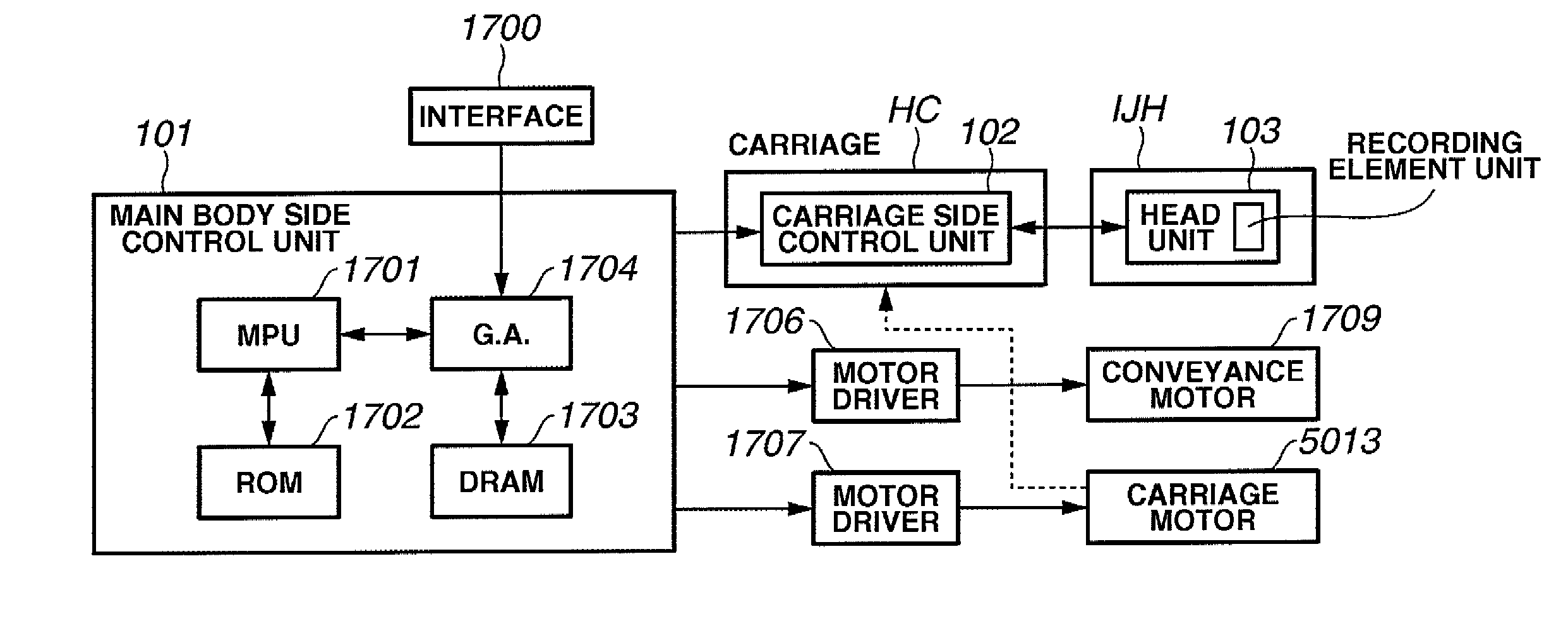
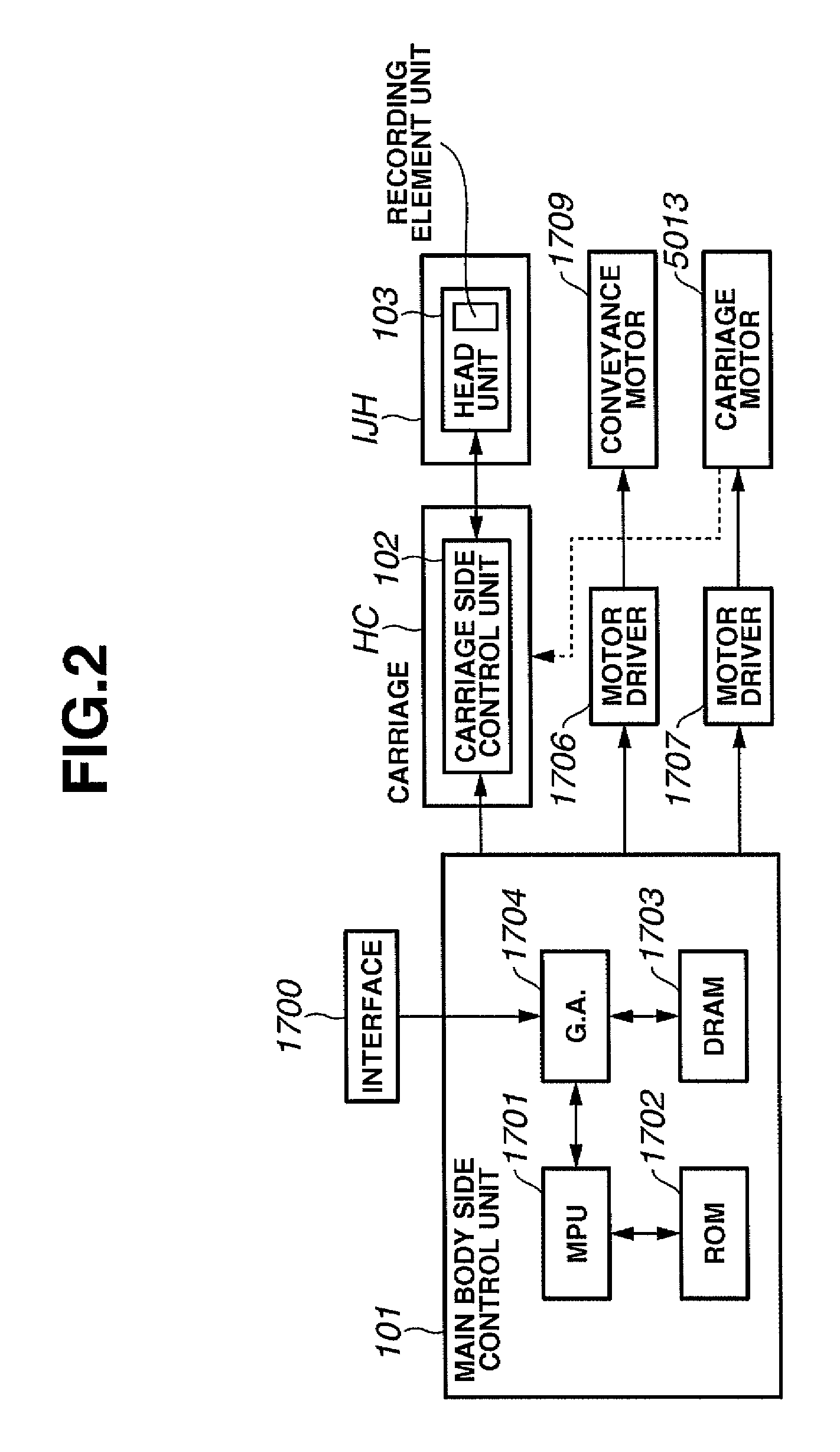
[0036]FIG. 11 schematically illustrates a characterizing portion of a configuration of the recording head IJH to which a first exemplary embodiment of the present invention can be applied. According to the present exemplary embodiment, a plurality of recording elements 2 (a line of 256 recording elements Seg. 0 to Seg. 255) are provided on an inkjet recording head substrate 1. Ink supply ports 14, adapted to supply ink to ink discharge nozzles (not shown) structurally provided above the recording elements, are formed on the substrate by performing anisotropic etching or sandblasting thereon.

[0037] The discharge ports of the ink discharge nozzles are provided on a side opposed to the recording element. Recording element columns 2 constituted by electrothermal elements (resistance elements) arranged in a line (the electrothermal elements of each recording element column can be arranged on double-level lines corresponding to a set of several nozzles) are disposed corresponding to the ...

second exemplary embodiment

[0055]FIG. 3 schematically illustrates a characteristic portion (i.e., a characteristic circuit part of a recording head substrate 1) of an inkjet recording head to which a second exemplary embodiment of the present invention is applicable.

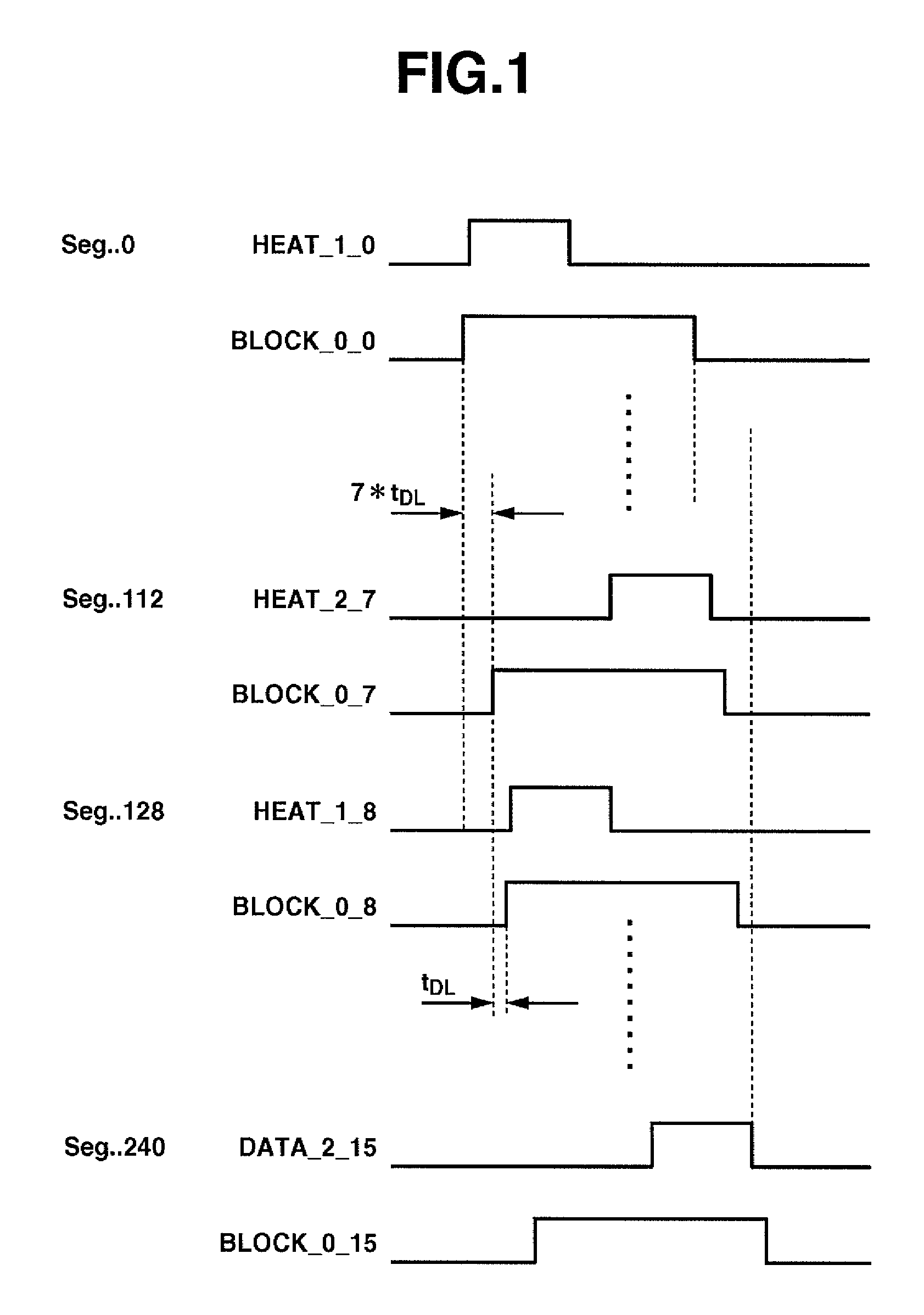
[0056] Differences from the first exemplary embodiment shown in FIG. 11 to the second exemplary embodiment are described below. A control circuit 6 divides the recording elements into blocks each having 32 nozzles, and selects one of the blocks. Also, the control circuit 6 performs time-divisional driving by inputting time-divisional control signals and by outputting time-divisional driving signals through system wires 7. The control circuit 6 is usually constituted by a decoder circuit or a shift register circuit. An AND-circuit column 8 is used to set an energization time during which electric current is fed to each of the recording elements by a driving pulse. The recording head according to the present embodiment is configured so that adjacen...


PUM


Abstract

A recording head circuit is configured to drive a plurality of recording elements by dividing the plurality of recording elements into a plurality of blocks. The circuit delays not only heat signals, which are used to drive the recording elements in each of the blocks, but also block signals. Consequently, noises are prevented from appearing due to overlapping of signals.

Description

BACKGROUND OF THE INVENTION [0001] 1. Field of the Invention [0002] The present invention relates to a recording head capable of performing stable printing, and to a recording apparatus adapted to perform recording using the recording head. [0003] 2. Description of the Related Art [0004] Various recording heads have been known, on which a plurality of recording elements are arranged in a line or in a plurality of lines. In the recording head of such a kind, several or tens of drive integrated circuits, each of which can simultaneously drive N recording elements as one block, are mounted on the same substrate. Among such recording heads, a recording head including a plurality of electrothermal conversion elements as recording elements, which generate discharge energy used to discharge ink from a discharge port, has been known. Some of such a recording head drives a large number of recording elements and needs a large amount of electric power to drive the recording elements. Additiona...

Claims


Application Information

Patent Timeline
Patent Type & Authority Applications(United States)
IPC IPC(8): B41J29/38
CPCB41J2/04528B41J2/04541B41J2/04543B41J2/04591B41J2/04573B41J2/0458B41J2/04581B41J2/04553
Inventor AKAMA, YUICHIROHAYASAKI, KIMIYUKIOGAWA, MASAHIKOTAKEI, YASUNORI
Owner CANON KK
Why Eureka
Try Eureka