Magnetic coupling pump device

A technology of magnetic coupling pump and pump chamber, applied in pump devices, pumps, non-variable capacity pumps, etc., can solve problems such as deformation or damage, pump efficiency drop, cost increase, etc., to prevent deformation or damage, prolong life, The effect of reducing the axial load

Inactive Publication Date: 2009-07-29
SANKYO SEIKI MFG CO LTD
View PDF6 Cites 0 Cited by
  • Summary
  • Abstract
  • Description
  • Claims
  • Application Information

AI Technical Summary

Problems solved by technology

Therefore, the thrust bearings 561, 562 in the impeller 510 have problems of deformation or damage, and a decrease in pump efficiency.
This problem can be solved to some extent if special thrust bearings 561, 562 are used, but the price of such thrust bearings 561, 562 is very high, so the cost increases

Method used


Image

  • Magnetic coupling pump device
  • Magnetic coupling pump device
  • Magnetic coupling pump device

Examples


Embodiment Construction

[0028] Next, a magnetic coupling pump device to which the present invention is applied will be described with reference to the drawings.

[0029] (the whole frame)

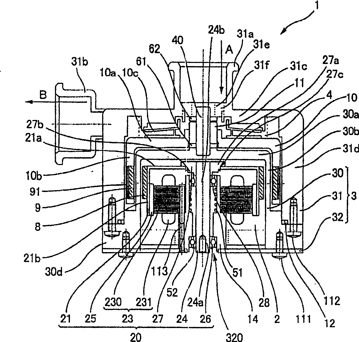
[0030] figure 1 It is a cross-sectional view of a magnetic coupling pump device to which the present invention is applied. exist figure 1 Among them, the magnetic coupling pump device 1 of this form has a casing 3, which includes a cup-shaped casing 31 with an open bottom, a cup-shaped partition wall 30 installed inside the casing 31, and an end that seals the opening below the partition wall 30. The plate 32 , the end face of the partition wall 30 and the end plate 32 are fixed by bolts 111 . Moreover, the end surface of the case 31 and the flange part 30d of the partition wall 30 are fixed by the bolt 112 in the state which sandwiched the O-ring 12. In the housing 31 , the inflow pipe portion 31 a opens upward, and the outflow pipe portion 31 b opens laterally.

[0031] In the case 3 configured in this wa...


PUM


Abstract

A magnetically coupled pump device (1) capable of miniaturization, comprising a motor chamber (2), a pump chamber (4) opposite to the motor chamber (2) across a partition wall (30), and in the motor chamber (2) An electric motor (20) is arranged inside, which includes: a stator (23), a motor rotating shaft (24), a rotor (21) held on the motor rotating shaft (24), and a rotor (21) held on the rotor (23) opposite to the stator (23). 21) on the rotor magnet (25), and the drive magnet (8) that remains on the rotor (21). A driven magnet (9) facing the driving magnet (8) across a partition wall (30), and an impeller (10) rotatable integrally with the driven magnet (9) are arranged in the pump chamber (4). The motor part has a "circumferentially opposite structure" in which the rotor magnet (25) is located on the outer peripheral side of the stator (23), and the magnetic coupling part has a "circumferentially opposed structure" in which the driven magnet (9) is located on the outer peripheral side of the drive magnet (8).

Description

technical field [0001] The invention relates to a magnetic coupling pump device which transmits impeller power by using magnetic coupling force. Background technique [0002] In the magnetic coupling pump device, in the motor chamber and the pump chamber separated by the partition wall, the motor chamber is configured with a motor, and the pump chamber is provided with an impeller, and the power of the motor is transmitted to the impeller by magnetic coupling force. Here, the conventional magnetic coupling pump device adopts the image 3 and Figure 4 2 structures shown. [0003] First, if image 3 As shown, in the magnetic coupling pump device 401 of the so-called circumferentially opposed structure type, the opening of the cup-shaped yoke 422 faces the pump chamber 404 and is connected to the upper end of the rotating shaft 424, and on the partition wall 430, the yoke is imitated. The cup shape of the iron 422 is formed with the bottomed cylindrical part 430b recessed to...

Claims


Application Information

Patent Timeline
Patent Type & Authority Patents(China)
IPC IPC(8): F04D13/02
Inventor 藤岛真
Owner SANKYO SEIKI MFG CO LTD
Why Eureka
Try Eureka