Optical lens assembly having an optical refractive index matching layer

a technology of optical refractive index and optical lens, applied in the field of optical lens assembly, can solve the problems of affecting image quality, affecting the outer edge of the lens, and reducing the overall image contras

Inactive Publication Date: 2015-08-13
LARGAN PRECISION
View PDF4 Cites 12 Cited by
  • Summary
  • Abstract
  • Description
  • Claims
  • Application Information

AI Technical Summary

Benefits of technology

[0023]In the optical lens assembly of the present invention, it is preferable that the ring-shaped optical component is a light shielding element.

Problems solved by technology

The unexpected light in an optical lens assembly may cause flare, ghost or a decrease in the overall image contrast and adversely affect the image quality.
The reflection from the interface between the outer edge of the lens and air is another problem to be solved in lens design.
For a lens made of any of such materials, the interface between the outer edge thereof and air causes the occurrence of full reflection easily and results in the formation of unexpected light in the lens assembly.

Method used


Image

  • Optical lens assembly having an optical refractive index matching layer
  • Optical lens assembly having an optical refractive index matching layer
  • Optical lens assembly having an optical refractive index matching layer

Examples


first embodiment

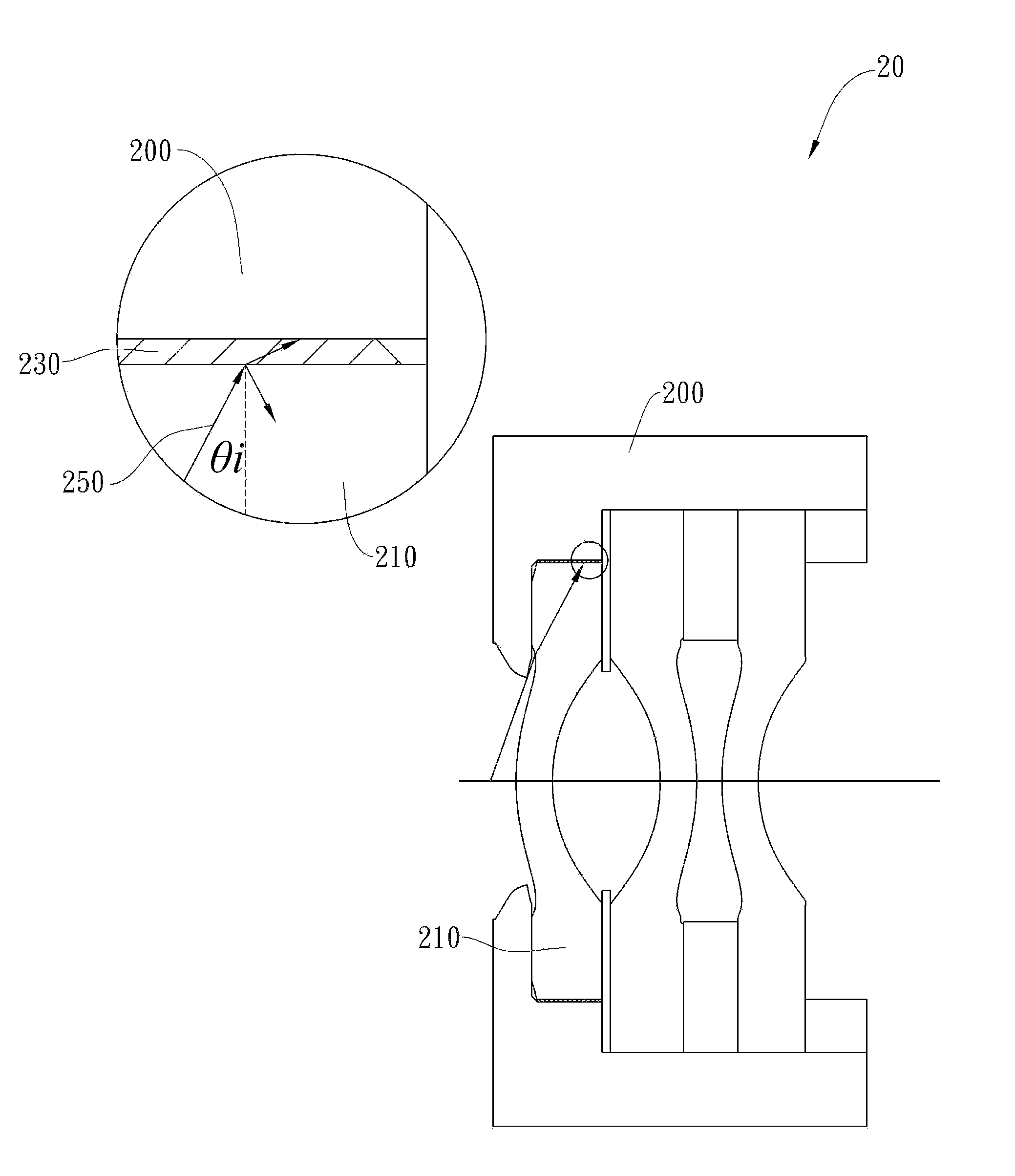
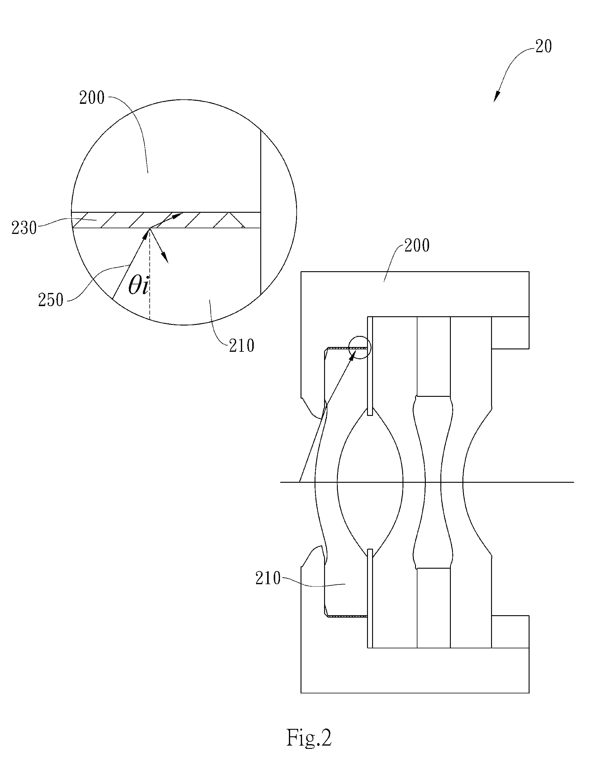
[0034]FIG. 2 is a partial view of an optical lens assembly 20 having an optical refractive index matching layer in accordance with the present invention. The optical lens assembly 20 comprises a lens barrel 200, a lens 210, and an optical refractive index matching layer 230 made of an optically transmissive material and connecting the lens barrel 200 and an outer edge of the lens 210. The optical refractive index matching layer 230 respectively contacts the lens barrel 200 and the outer edge of the lens 210 to prevent the formation of an interface between the outer edge of the lens 210 and air, which would exhibit a high degree of refractive index variance, and thereby to reduce the reflection of light from the interface of the outer edge of the lens. When light, such as light 250 in FIG. 2, is incident to the optical lens assembly 20 at a larger angle from the edge of the field of view, the light is incident to an upper edge of the lens 210 and then partially refracted and reflecte...

second embodiment

[0053]In this embodiment, the first lens element 410 has a bulging first lens element fitting surface 480 (which consists of a first abutment section 481 and a second abutment section 482 of the first lens element 410, as shown in FIG. 4B) lap joining a second lens element fitting surface 470 (which consists of a first abutment section 471 and a second abutment section 472 of the second lens element 420, as shown in FIG. 4B) of the second lens element 420 (the first abutment section 481 of the first lens element 410 abuts against the first abutment section 471 of the second lens element 420, and the second abutment section 482 of the first lens element 410 abuts against the second abutment section 472 of the second lens element 420). In this lap-joint structure, the first lens element 410 is in direct contact with the second lens element 420, thus the light (for example, light 450 in FIG. 4A) incident to the first lens element 410 at a larger angle will pass the interface via which ...


PUM


Abstract

The present invention provides an optical lens assembly, comprising: a lens barrel made of plastic material and having a lens insertion opening and a lens barrel central axis, the lens barrel accommodating a first lens element with refractive power, a second lens element with refractive power made of plastic material, a third lens element with refractive power, and an optical refractive index matching layer disposed between the lens barrel and the second lens element, and respectively connecting the lens barrel and the second lens element; wherein the first lens element is disposed farther from the lens insertion opening than the second lens element, and the second lens element is disposed farther from the lens insertion opening than the third lens element; and wherein there is an air space between any two adjacent lens elements on the lens barrel central axis.

Description

BACKGROUND OF THE INVENTION[0001]1. Field of the Invention[0002]The present invention relates to an optical lens assembly, and more particularly, to an optical lens assembly having an optical refractive index matching layer.[0003]2. Description of the Prior Art[0004]The unexpected light in an optical lens assembly may cause flare, ghost or a decrease in the overall image contrast and adversely affect the image quality. In addition to the multiple reflections between the lenses, the unexpected light may be the result of reflections from other discontinuous interfaces in the lens assembly, such as the reflection from the interface between the outer edge of the lens and air, or the reflection from the inner edge of the lens barrel. To eliminate the multiple reflections, the lenses in a modern lens assembly are usually coated with multiple anti-reflection layers to increase the transmittance thereof and reduce the unexpected reflections therebetween. To eliminate the reflection from the...

Claims


Application Information

Patent Timeline
Patent Type & Authority Applications(United States)
IPC IPC(8): G02B7/02G02B7/00
CPCG02B7/026G02B7/021G02B7/022G02B27/0018
Inventor HUANG, YEO-CHIH
Owner LARGAN PRECISION
Why Eureka
Try Eureka