
Method of analyzing an image

a technology of image and method, applied in image analysis, image enhancement, instruments, etc., can solve the problems of high computational load during feature extraction and classification, the difficulty of dealing with vessel calcification, and the pitfall of watershed methods

Active Publication Date: 2015-08-13
AGFA NV
View PDF1 Cites 4 Cited by
  • Summary
  • Abstract
  • Description
  • Claims
  • Application Information

AI Technical Summary

Benefits of technology

The patent text explains that it is beneficial to use a trained classifier to decide which type of item to assign to a specific area of a tree. This helps improve the efficiency and accuracy of identifying and organizing data.

Problems solved by technology

155, 1999 uses an iterative region growing approach, but has trouble in dealing with vessel calcifications.
However, one pitfall of these (watershed methods), as stated in U.S. Pat. No. 6,985,612, is oversegmentation.
The watershed techniques commonly generate too much basins, resulting in a high computational load during feature extraction and classification.
There have been attempts to mitigate this, but the watershed transform remains a very costly operation on contemporary CTA (Computed Tomography Angiography) datasets.
Therefore, the use of the watershed transform might be unwarranted when aiming for a fast algorithm.
It is due to partial volume effects and the limited resolution of CT modalities that they may appear to touch in CTA studies.
Finding that right intensity level however, is not an easy task, which is why most existing approaches use interactively controlled threshold levels.

Method used


Image

  • Method of analyzing an image
  • Method of analyzing an image
  • Method of analyzing an image

Examples


Embodiment Construction

[0026]In this detailed description a preferred embodiment of the method of the present invention is explained with regard to the removal of bone tissue in a CTA image. CTA volume density is expressed in Hounsfield units.

[0027]Taking into consideration the computational complexity of thresholds with respect to that of watersheds, and the relative ease at which they can be parallelized, a threshold based segmenter is used in the proposed automated bone removal technique.

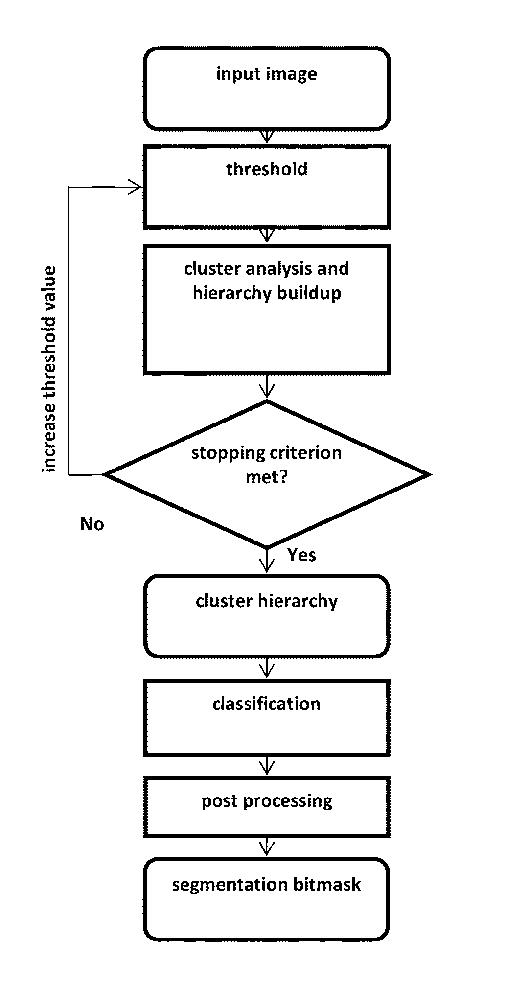
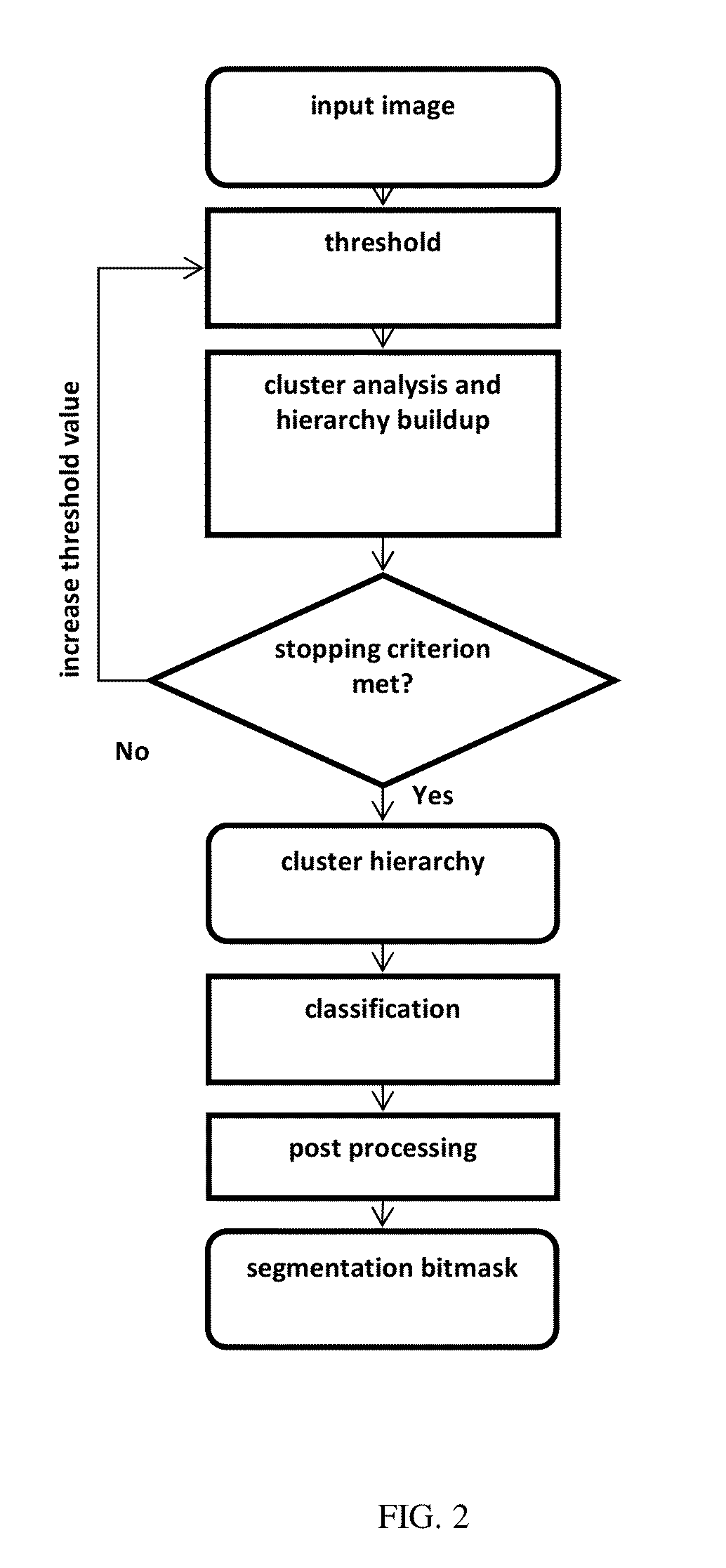
[0028]A preferred method of the present invention is illustrated in FIG. 1. The method in general comprises a segmentation stage and a classifying step.

[0029]The segmentation stage includes an iterative process of thresholding and cluster analysis.

Iterative Thresholding:

[0030]The threshold operations are performed iteratively, with increasing threshold value each time: the mask of voxels that remain after each threshold operation is fed into the new threshold operation, at each stage reducing the computational cost as ...


PUM


Abstract

An image is segmented by subjecting the image to an iterative thresholding operation, and a hierarchical representation of clusters is obtained by analyzing the results of each of the iterative thresholding steps to find clusters of adjacent image elements. A type class is assigned to a leaf cluster of the hierarchical representation and the assigned class is propagated towards the top of the hierarchical representation. Then a mask is generated marking the locations of image elements contained in the top ancestral clusters of a specific type.

Description

CROSS-REFERENCE TO RELATED APPLICATIONS[0001]This application is a 371 National Stage Application of PCT / EP2013 / 069324, filed Sep. 18, 2013. This application claims the benefit of U.S. Provisional Application No. 61 / 733,439, filed Dec. 5, 2012, which is incorporated by reference herein in its entirety. In addition, this application claims the benefit of European Application No. 12186753.5, filed Oct. 1, 2012, which is incorporated by reference herein in its entirety.BACKGROUND OF THE INVENTION[0002]1. Field of the Invention[0003]The present invention relates to a method of analyzing an image represented by a digital image representation.[0004]2. Description of the Related Art[0005]In a radiocontrast medical imaging setting, a patient is administered a contrast agent to increase the radiodensity of some lumen in the body. In a reconstruction of angiographic X-ray projections, the vessel tree will therefore have a density similar to that of bony tissue. As such, when displaying only h...

Claims


Application Information

Patent Timeline
IPC IPC(8): G06T7/00G06T5/00
CPCG06T7/0012G06T5/005G06T7/0081G06T7/0093G06T2207/20148G06T2207/20016G06T2207/20072G06T2207/20081G06T2207/30008G06T2207/10081G06T2207/30101G06T7/11G06T7/162G06T7/136G06T5/77
Inventor MERCKX, GERTCANT, JEROEN
Owner AGFA NV
Learn More