Rear sub frame of automotive vehicle

Active Publication Date: 2015-08-20
MAZDA MOTOR CORP
View PDF4 Cites 1 Cited by
  • Summary
  • Abstract
  • Description
  • Claims
  • Application Information

AI Technical Summary

Benefits of technology

[0005]The present invention has been devised to solve the above-described problems of the conventional rear sub frame, and its object is to provide a rear sub frame of an automotive vehicle which c

Problems solved by technology

In this case, since complicated vibration modes are caused by the shape of the bending portion of the cross member, it may be difficult to improve the NVH performance properly.
Further, it is necessary to rein

Method used


Image

  • Rear sub frame of automotive vehicle
  • Rear sub frame of automotive vehicle
  • Rear sub frame of automotive vehicle

Examples


Embodiment Construction

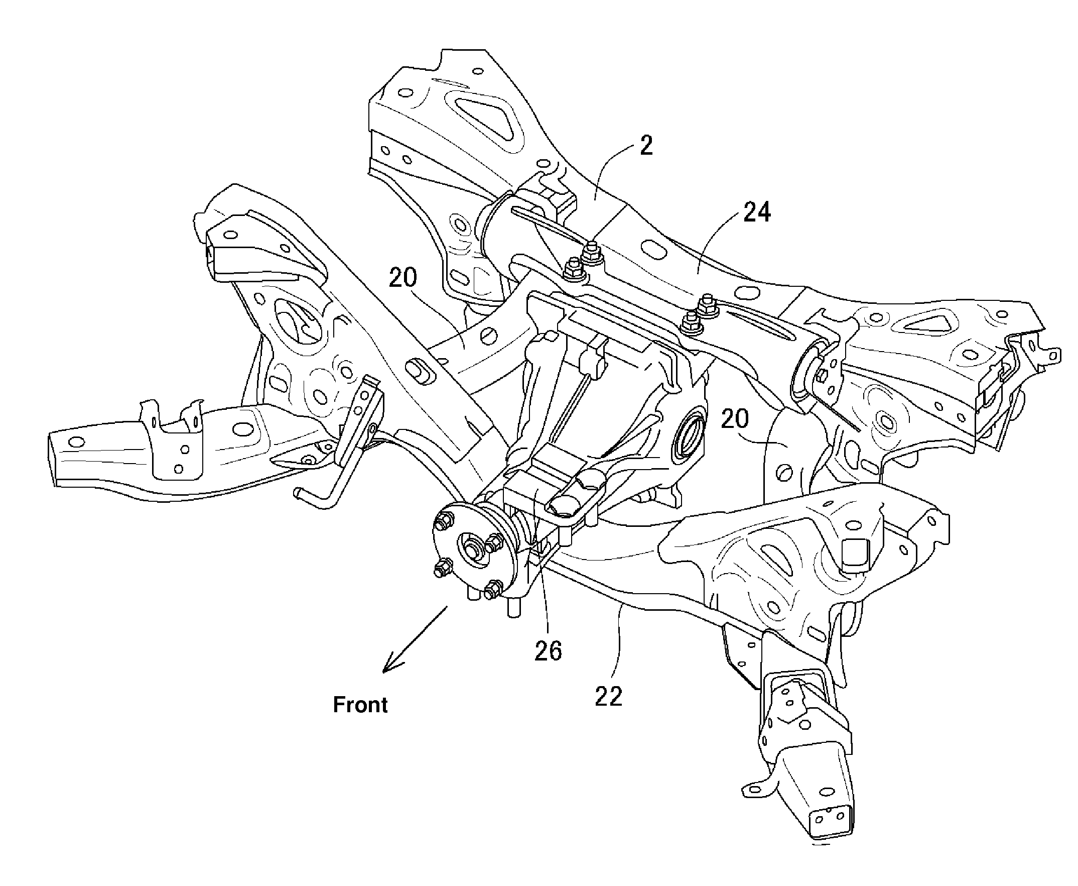
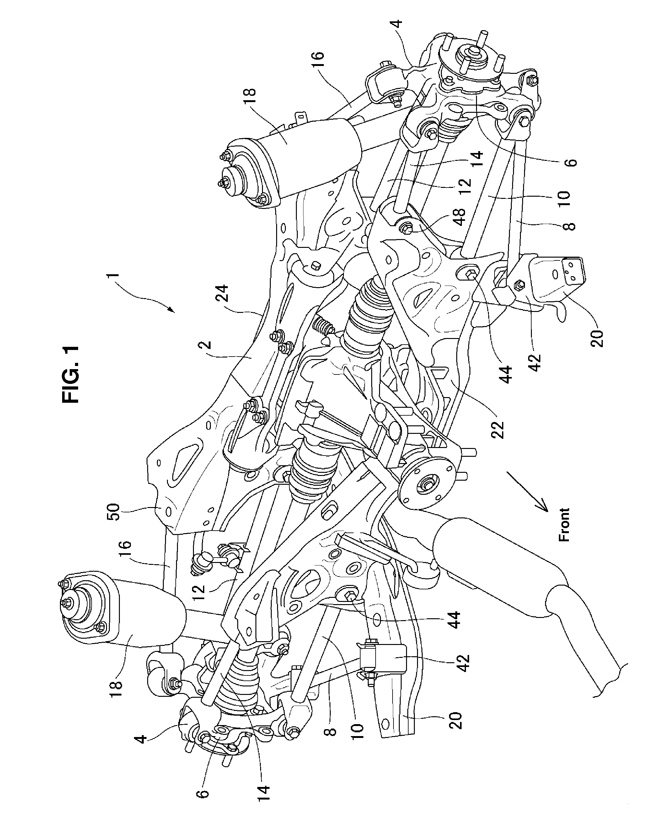
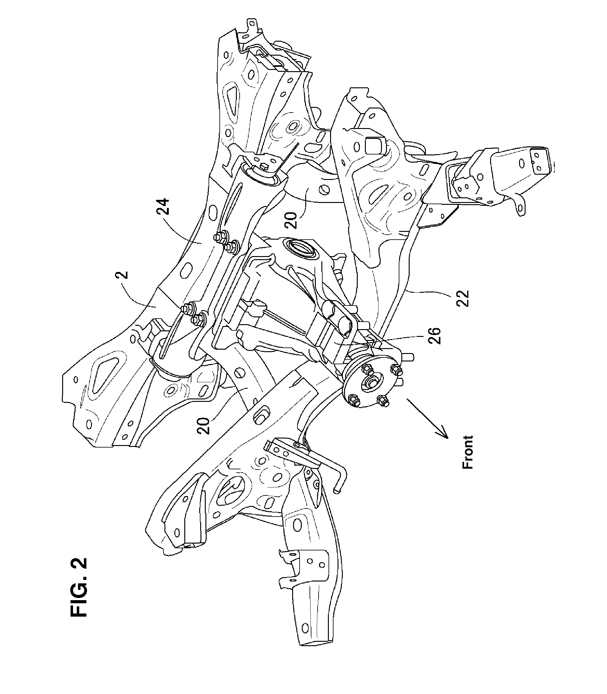
[0026]Hereinafter, a rear sub frame of an automotive vehicle according to an embodiment of the present invention will be described referring to the accompanying drawings. A rear suspension device to which the rear sub frame of the automotive vehicle according to the present invention is applied will be described referring to FIG. 1 first. FIG. 1 is a perspective view of the rear suspension device to which the rear sub frame of the automotive vehicle according to the embodiment of the present invention is applied, when viewed obliquely from the front and the left of a vehicle body.

[0027]In FIG. 1, reference character 1 denotes the rear suspension device. The rear suspension device 1 of the present embodiment is provided at a rear-wheel drive vehicle in which a rear differential is provided below a rear portion of a vehicle body and rear wheels are driven. The rear suspension device 1 mainly comprises a rear sub frame 2 and a pair of rear suspensions 4 which are provided on both sides...


PUM


Abstract

A rear sub frame comprising a pair of side members, a front cross member, and a rear cross member. The front cross member is configured in substantially a V shape in a front view such that the front cross member slants continuously from both end portions thereof toward a central portion, in a vehicle width direction, thereof which is located below a rear differential, and that a center position, in the vehicle width direction, of a bottom portion of the front cross member which corresponds to an apex portion of the V shape is offset from a center of a vehicle body in the vehicle width direction toward a specified side which matches an offset-arrangement side of a ring gear arranged in the rear differential.

Description

BACKGROUND OF THE INVENTION[0001]The present invention relates to a rear sub frame of an automotive vehicle, and in particular relates to the rear sub frame of the automotive vehicle, which is attached to a kick-up portion and rear frames of a vehicle body at a rear portion of the vehicle body where a rear differential is provided.[0002]An assembly of an automotive vehicle, in which links and arms of a rear suspension are attached to a rear sub frame and then this rear sub frame is attached to a kick-up portion and rear frames of a vehicle body, is known.[0003]Herein, the rear sub frame which comprises a pair of side members extending in a vehicle longitudinal direction at both sides, in a vehicle width direction, of the vehicle body and cross members extending in the vehicle width direction and interconnecting the pair of side members is known, for example. The rear sub frame of the automotive vehicle having rear wheels as driving wheels, in which a front cross member of the cross ...

Claims


Application Information

Patent Timeline
IPC IPC(8): B62D21/11B60K17/16
CPCB60K17/165B62D21/11B60G2200/144B60G2200/156B60G2204/15B60G2204/19B60G2206/604B60G2200/184
Inventor OKUYAMA, KAZUHIROANDOU, FUMITAKAHIRAMATSU, MASAYANISHINO, MAKOTO
Owner MAZDA MOTOR CORP
Why Eureka
Try Eureka