
Wireless light board

a light board and wireless technology, applied in the field of light boards, can solve the problems of inconvenient battery replacement, inconvenient installation of cables for powering infrared switches or ultrasonic switches, and inability to meet the needs of users, etc., and achieve the effect of convenient battery replacement and easy installation

Inactive Publication Date: 2015-08-20
ZEALIO ELECTRONICS
View PDF14 Cites 13 Cited by
  • Summary
  • Abstract
  • Description
  • Claims
  • Application Information

AI Technical Summary

Benefits of technology

The present invention aims to offer a thin, waterproof, power-efficient, simple to install and replace batteries easy wireless light board.

Problems solved by technology

These kinds of switches consume much power, hence they need to be powered by electricity of the vehicle.
However, the cables for powering the infrared switches or the ultrasonic switches are hard to install.
Besides, the infrared switches or the ultrasonic switches normally have shorter life cycle due to high power consumption.

Method used


Image

  • Wireless light board
  • Wireless light board
  • Wireless light board

Examples


Embodiment Construction

[0015]The present invention will be described in detail with embodiments below. However, it should be understood that these embodiments are only to exemplify the present invention but not to limit the scope of the present invention.

[0016]The present invention discloses a wireless light board whose novel design can realize waterproofness, compactness, easy installation, convenient battery replacement, and high power efficiency. Some embodiments will be described in detail in cooperation with the attached drawings to exemplify the present invention. In addition to these embodiments, the present invention also widely applies to various other embodiments. Any substitution, modification or variation easily derived from the embodiments described in the specification is to be also included within the scope of the present invention, which is mainly according to the claims stated below. Many specified details are provided in the specification to enable the readers to more clearly understand ...


PUM


Abstract

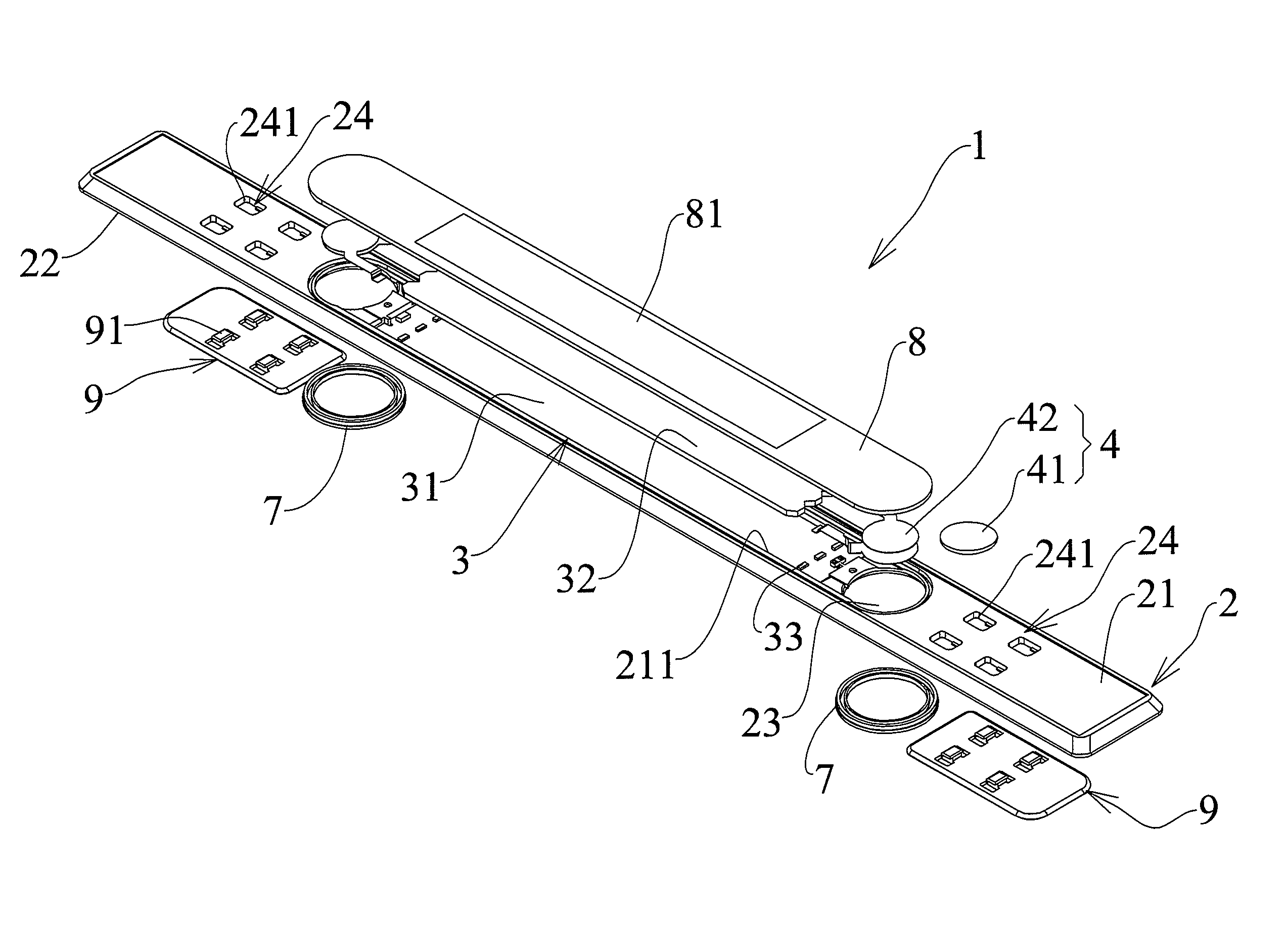
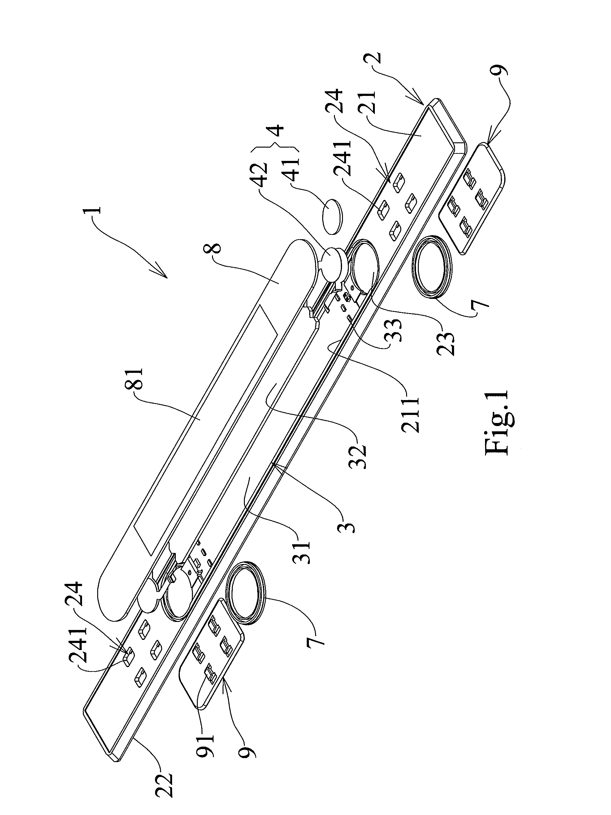
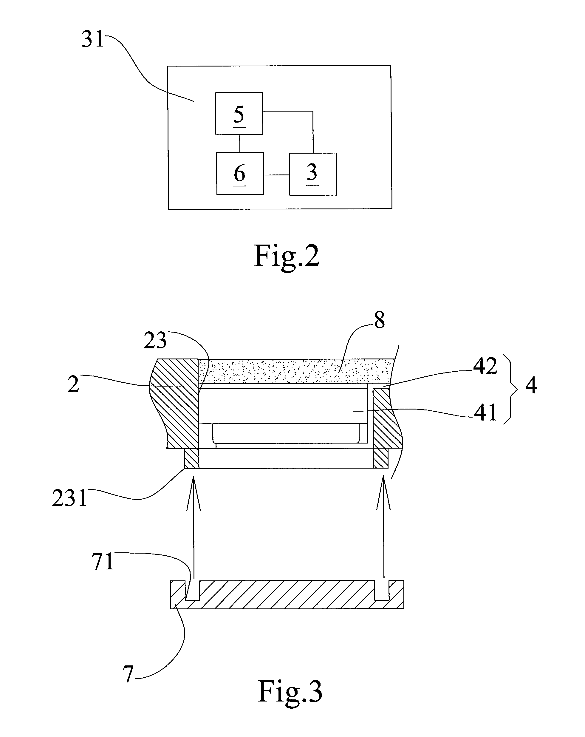
A wireless light board is disclosed herein. The present invention comprises a baseplate, a backlight module, a power module, a proximity sensor module, a control module, at least one bottom cover, and a top cover. The baseplate has a recess and a power source accommodation hole to respectively accommodate the backlight module and the power module. The control module is arranged on a circuit board and electrically connected with the backlight module and the proximity sensor module to turn on / off the backlight module. The bottom cover removably covers the power source accommodation hole. The top cover covers at least the backlight module and the power module and has a first light-permeable region above the backlight module. Thereby, the wireless light board is slim, waterproof, power-saving, easy to install, and convenient for battery replacement.

Description

BACKGROUND OF THE INVENTION[0001]1. Field of the Invention[0002]The present invention relates to a light board, particularly to a wireless light board.[0003]2. Description of the Prior Art[0004]In some of the automotive vehicles, usually is embedded a light-emitting board on the threshold of the floor in order to form a visual effects pedal. In general, the light-emitting comprises a plurality of LEDs (Light Emitting Diodes) or a lamp as an illuminant disposed behind the shielding sheet openings to produce the visual effect, and these openings are usually designed for the automobile brand recognition including text or graphics.[0005]In conventional lighting welcome pedals, infrared switches or ultrasonic switches are used to turn on / off the lights. These kinds of switches consume much power, hence they need to be powered by electricity of the vehicle. However, the cables for powering the infrared switches or the ultrasonic switches are hard to install. Besides, the infrared switches...

Claims


Application Information

Patent Timeline
Patent Type & Authority Applications(United States)
IPC IPC(8): F21V23/00G01V3/08G01V3/10F21S9/02F21V8/00
CPCG09F13/04G09F13/08G09F2027/001B60Q3/82B60Q3/64B60Q3/217G02B6/0083G02B6/0093G09F13/044B60Q1/325B60Q2900/30G02B6/0068
Inventor CHENG, C.P.GUO, PAO-LIN
Owner ZEALIO ELECTRONICS
Learn More