
Water-tight micro-switch

Inactive Publication Date: 2015-08-20
JOHNSON ELECTRIC INTERNATIONAL AG
View PDF7 Cites 7 Cited by
  • Summary
  • Abstract
  • Description
  • Claims
  • Application Information

AI Technical Summary

Benefits of technology

The invention is about a micro-switch that prevents media from entering through typical pass-through points between the plunger and bellows, and seals the interface between the switch cover and switch base to prevent leaking of liquids and moisture. The switch cover is made from the same material as the switch base and can form a material bond through glueing or injection-molding. In this design, the switch cover is flexible and can cope with the necessary actuating travel over the long term.

Problems solved by technology

Stresses caused by climate, media, pressurized water or switching under water or covered by fluids constitute stresses, which switches as unprotected components, frequently cannot withstand.
Problems arise, however, when an actuating element is run through the switch cover, because a weak point is created in this spot.
Admittedly sealing elements, such as bellows, are provided to seal the joint between the cover and the actuating element but sealing elements of this kind tend to start leaking, in particular with longer-term use.

Method used


Image

  • Water-tight micro-switch
  • Water-tight micro-switch
  • Water-tight micro-switch

Examples


Embodiment Construction

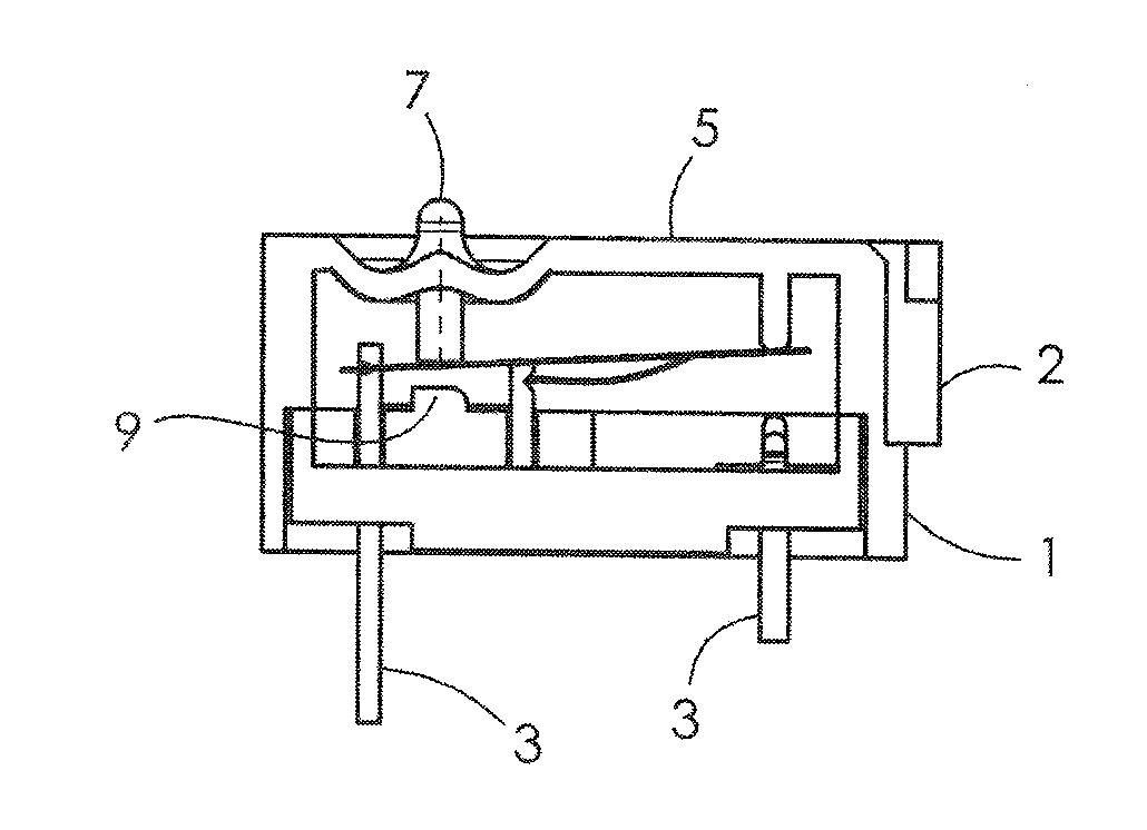
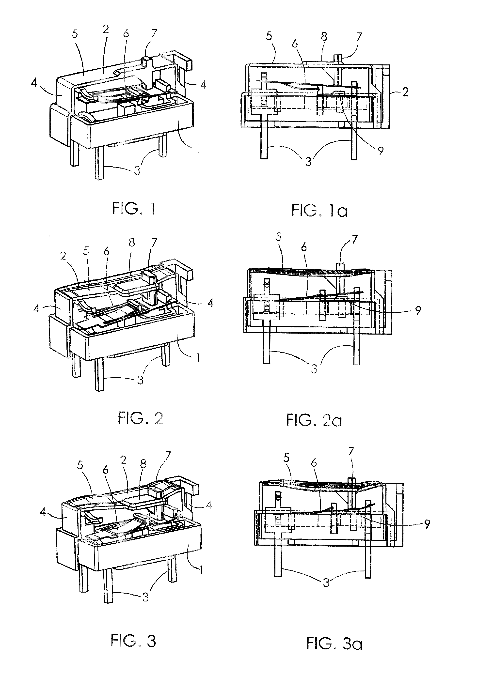
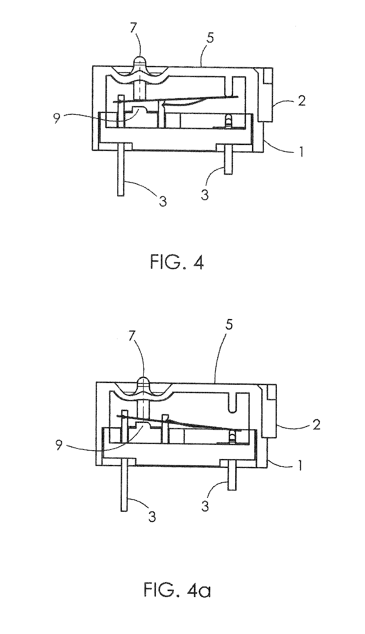
[0028]The micro-switch shown in FIGS. 1 to 3a comprises a switch base 1 and a switch cover 2. The switch base 1 has the constructional shape of an upwardly open trough, the floor of the switch base 1 is penetrated by contacts 3. The portions of the contacts extending from the base form terminals for the switch. The switch cover 2 has a substantially rectangular shape, with lateral wall sections 4 and a top wall section 5. The base 1 and the cover 2 form a housing for contacts 3 as well as for switch components 6.

[0029]The micro-switch shown in the Figures is, according to the invention, equipped with a one-piece switch cover 2. FIG. 1 shows that the switch cover 2 is formed in one piece with a plunger 7. The plunger 7 forms an actuating element for the switch component 6 inside the micro-switch. The plunger 7 has an outwardly protruding section as well as an inwardly protruding section, wherein the inwardly protruding section is supported by a reinforcement 8. The switch base 1 supp...


PUM


Abstract

A micro-switch has a housing formed by a switch base and a switch cover. The switch has an actuating element for operating a switching mechanism disposed within the housing. The switch cover and the actuating element are formed as a one-piece component, preferably by molding. The switch cover is bonded to the switch base. Thus a seal between the housing and the actuating element is eliminated.

Description

CROSS REFERENCE TO RELATED APPLICATIONS[0001]This non-provisional patent application claims priority under 35 U.S.C. §119(a) from Patent Application No. DE102014002104.1 filed in Germany on Feb. 15, 2014, and from Patent Application No. DE102014005433.0 filed in Germany on Apr. 10, 2014, the entire contents of which are hereby incorporated by reference.FIELD OF THE INVENTION[0002]This invention relates to an electrical switch and in particular, to a water-tight micro-switch.BACKGROUND OF THE INVENTION[0003]In many applications switches are required to reliably function under difficult environmental conditions. Such applications are typical for automotive, nautical, medical, and industrial environments. Stresses caused by climate, media, pressurized water or switching under water or covered by fluids constitute stresses, which switches as unprotected components, frequently cannot withstand.[0004]The switch base and the switch cover form the housing of the micro-switch accommodating a...

Claims


Application Information

Patent Timeline
IPC IPC(8): H01H9/04
CPCH01H2229/044H01H9/04H01H13/06H01H13/14H01H13/36H01H2011/0081
Inventor KOEPSELL, MARTIN
Owner JOHNSON ELECTRIC INTERNATIONAL AG
Learn More