
Shock absorber

Inactive Publication Date: 2015-08-27
AOPEN
View PDF12 Cites 4 Cited by
  • Summary
  • Abstract
  • Description
  • Claims
  • Application Information

AI Technical Summary

Benefits of technology

The shock absorber described in this patent improves the ability of a computer to pass industry vibration tests. It includes a buffer plate and absorbing elements between the load and the assembling frames. The design also includes narrower widths on the absorbing bodies to easily tune the first absorbing element to intended deformation. The elastic deformation cuts off vibration waves and decreases vibration intensity to enhance the effects of shock absorption.

Problems solved by technology

Among these computer components, the disk is likely to be disturbed by the vibration because the disk uses the heads to read and write the data in the storage area.
Therefore, the disk may be damaged or the transmission efficiency of the disk may be affected negatively.
Most of the shock absorbers use an elastic washer because of cost considerations.
However, the shock absorber using the washer is not able to pass industry computer vibration tests because the specifications now are more stringent.

Method used


Image

  • Shock absorber
  • Shock absorber
  • Shock absorber

Examples


Embodiment Construction

[0018]In the following detailed description, for purposes of explanation, numerous specific details are set forth in order to provide a thorough understanding of the disclosed embodiments. It will be apparent, however, that one or more embodiments may be practiced without these specific details. In other instances, well-known structures and devices are schematically shown in order to simplify the drawing.

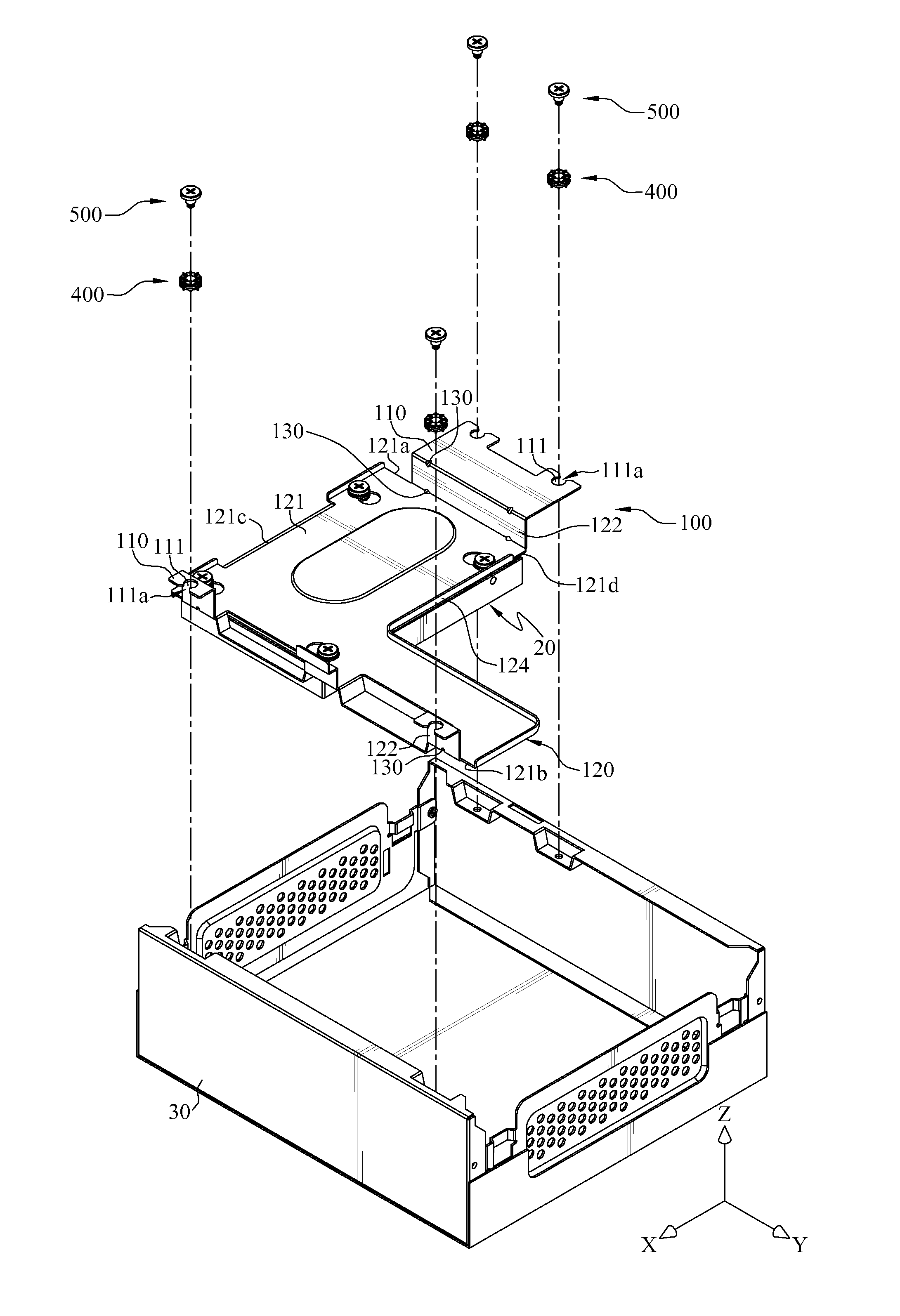
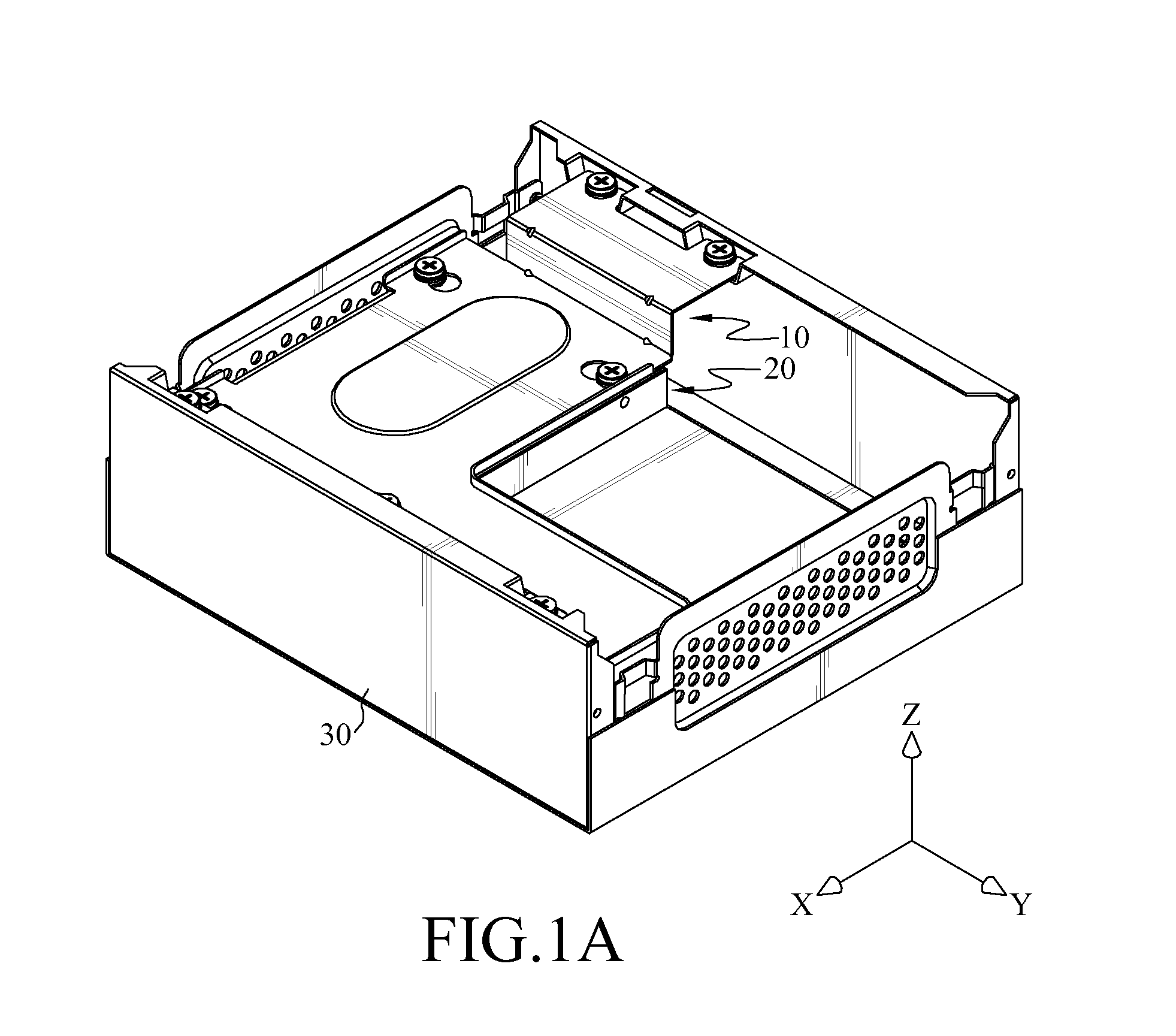
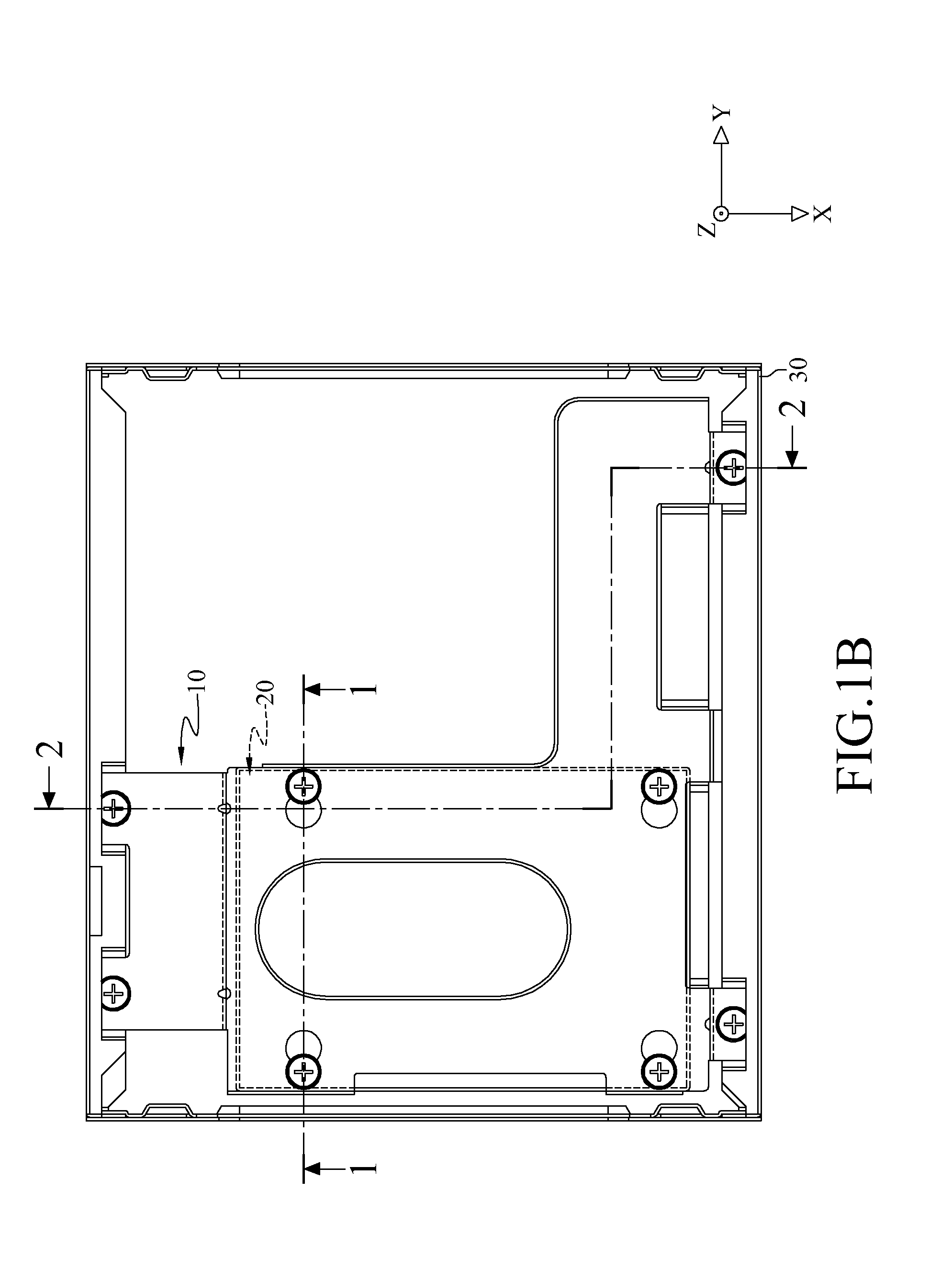
[0019]FIG. 1A is a perspective view of a shock absorber, a case and a load according to a first embodiment. FIG. 1B is a top view of FIG. 1A. FIG. 2A is an exploded view of an assembling element and the case in FIG. 1A. FIG. 2B is an exploded view of the assembling element and the load in FIG. 2A. FIG. 3 is a cross-sectional view of the assembling element in FIG. 1A.

[0020]In this embodiment, a shock absorber 10 is configured to install a load 20 on a case 30 of electronic device. The shock absorber 10 is configured to dissipate the vibration on the load 20 and this method of dissipa...


PUM


Abstract

A shock absorber includes assembling element, absorbing element and locking element. The assembling element includes assembling plate and buffer plate. The assembling plate is connected to the buffer plate. The buffer plate has assembling hole. The absorbing element has absorbing body and convex part. The absorbing body has opening hole. The absorbing body is detachably installed on the assembling hole, and the convex part is located on the absorbing element. The locking element has head part, protruding part and threaded part. The head part has limit surface. The protruding part protrudes from the head part and has limit surface. The threaded part protrudes from limit surface. The locking element passes through the first opening hole. The threaded part is used to fix a load to make the limit surface being abutted on the load, which makes the absorbing elements being elastically clamped between the limit surface and the load.

Description

CROSS-REFERENCE TO RELATED APPLICATIONS[0001]This non-provisional application claims priority under 35 U.S.C. §119(a) on Patent Application No(s). 103203480 filed in Taiwan, R.O.C. on 2014 Feb. 27, the entire contents of which are hereby incorporated by reference.BACKGROUND[0002]1. Technical Field[0003]The disclosure relates to a shock absorber, more particularly to a shock absorber for an electronic device.[0004]2. Related Art[0005]With the advance of technology, computers are getting more and more powerful and are more important than ever before. A current computer system mainly includes a case, a main board, a disk, and a power supply. Among these computer components, the disk is likely to be disturbed by the vibration because the disk uses the heads to read and write the data in the storage area. The heads may collide with the storage area if being influenced by the vibration. Therefore, the disk may be damaged or the transmission efficiency of the disk may be affected negativel...

Claims


Application Information

Patent Timeline
IPC IPC(8): F16F15/08F16M13/02
CPCF16M13/02F16F15/08F16F1/376
Inventor WANG, JO-CHIAO
Owner AOPEN
Learn More