Saggar assembly

a technology for saggars and parts, applied in the direction of furnace components, lighting and heating apparatus, furnaces, etc., can solve the problems of difficult stacking, saggars may even break, and are not economically feasible to repair such saggars

Active Publication Date: 2015-08-27
IMERTECH SAS
View PDF8 Cites 19 Cited by
  • Summary
  • Abstract
  • Description
  • Claims
  • Application Information

AI Technical Summary

Benefits of technology

[0018]In one embodiment, each of the base and side elements may or may not be constituted of separate element portions which in an assembled status may be secured together to form the respective element.

Problems solved by technology

Conventional saggars have a tendency to expand and contract as they are subjected to extreme temperature variations, and they often change shape, making them difficult to stack, or they may even break.
It is not economically feasible to repair such saggars.
In many cases, saggars are used in heat treatments involving very rapid heating and cooling, such that high temperature gradients may appear within the saggars, leading to cracking.
Furthermore, corrosion resistance in extreme temperatures is a general problem with saggars.
Since the base plate merely rests on the said floor supporting flanges, the assembled saggar is unstable.
Furthermore, the appearance of gaps between the base and wall sections is inevitable, making this unsuitable for particulate loads, for example in powder calcinations.
Despite the optional presence of gaps between the said flanges and flange-receiving sockets, which are intended to avoid the formation of thermal stresses, this does not solve the problem of upper size limits for the saggars.
The state of the art therefore constitutes a problem.

Method used


Image

  • Saggar assembly
  • Saggar assembly
  • Saggar assembly

Examples


Embodiment Construction

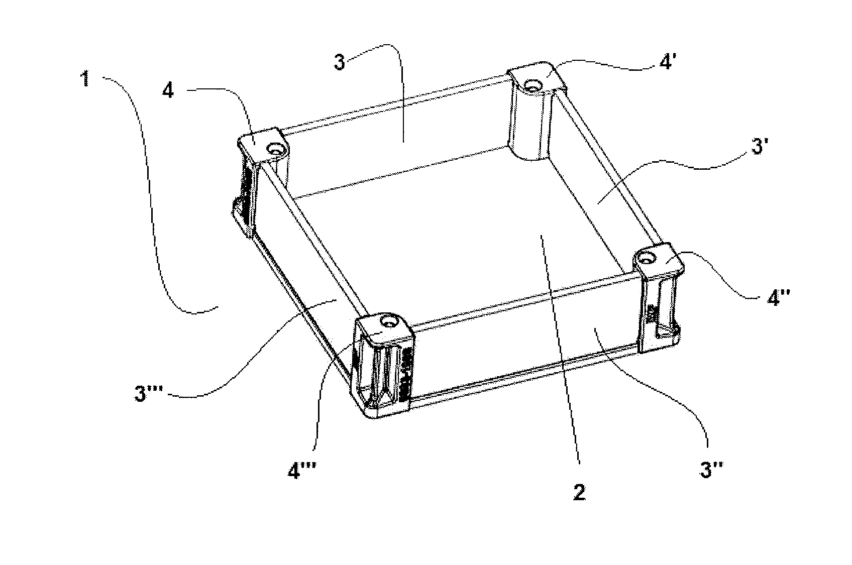
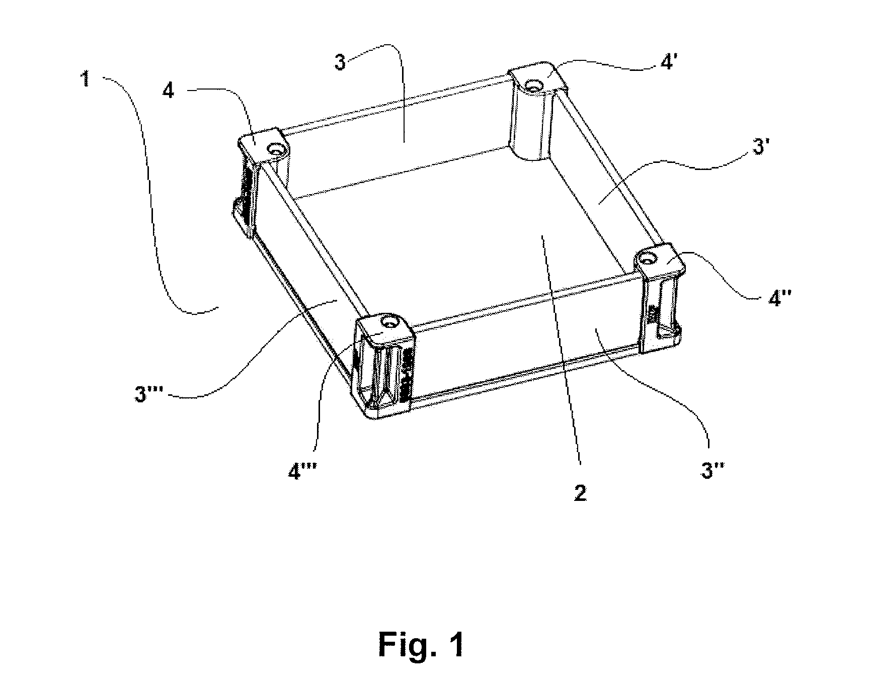
[0034]FIG. 1 shows a saggar 1 in an assembled state, as obtained from an assembly according to the present invention. There is a first base element 2 facing the inside of the box-shaped saggar 1. Four side elements 3, 3′, 3″, 3′″ are secured to the first base element 2 using four corner elements 4, 4′, 4″, 4′″. An optional second base element and screws cannot be seen in this perspective in the assembled state.

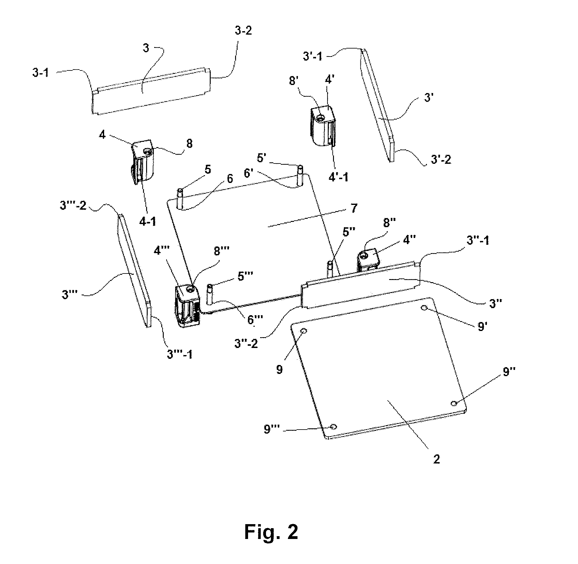
[0035]FIG. 2 shows all the elements of an assembly according to the present invention in a view intended to show one way of assembling the elements of the assembly in order to form a box-shaped saggar 1. Fasteners 5, 5′, 5″, 5′″ have been inserted into holes 6, 6′, 6′″ located in the vicinity of the corners of the optional second base element 7. The first base element 2, side elements 3, 3′, 3″, 3′″ and corner elements 4, 4′, 4″, 4′″ are also shown. The side elements 3, 3′, 3″, 3′″ each comprise rectangular extensions 3-1, 3-2, 3′-1, 3′-2, 3″-1, 3″-2, 3′″-1, 3′″-2, at each of ...


PUM


Abstract

An assembly for providing a saggar for use in high temperature applications, may include a first substantially rectangular base element and two sets of two substantially rectangular side elements, wherein the side elements of each set of side elements have at least one dimension corresponding to dimensions of first and second opposite edges of the base element. The assembly may also include four corner elements and fasteners, wherein the base element and the side elements are configured to be assembled into a box-shaped saggar and secured to one another using the corner elements and the fasteners, and wherein the first base element is made of a corrosion resistant material.

Description

FIELD OF THE INVENTION[0001]The invention concerns assemblies for assembling saggars for use in high temperature treatment, for example, the firing of ceramics, metal, powder calcinations or isolation foam manufacturing.BACKGROUND OF THE INVENTION[0002]Saggars are ceramic, box-like containers used in the firing of pottery to enclose or protect ware in kilns, or in powder calcinations for holding a powder to be calcined, or in isolation foam manufacturing for carrying the load, or in metal heat treatment. Traditionally, saggars were made primarily from fireclay. Saggars are used to protect or safeguard their load from open flame, smoke, gases and kiln debris. Modern saggars are made of various types of tailored ceramics such as for example alumina ceramics, cordierite ceramics, mullite ceramics, zirconia ceramics, magnesia ceramics, alumina-magnesia spinel ceramics, fused silica ceramics, aluminatitanate ceramics and silicon carbide ceramics.[0003]Traditionally, saggars in commercial...

Claims


Application Information

Patent Timeline
Patent Type & Authority Applications(United States)
IPC IPC(8): F27D5/00
CPCF27D5/0012F27D5/0006
Inventor SONNTAG, ANDREASKISS, SANDOR
Owner IMERTECH SAS
Why Eureka
Try Eureka