Dual-band passively athermal optical lens system

a passive athermal and optical lens technology, applied in the field can solve the problems of difficult to locate imaging or optical lens systems, compound imaging problems of both mid-wave infrared and long-wave infrared wavelengths, and achieve the effect of not significantly increasing the overall weight of optical lens systems, facilitating corresponding compensation, and strong and durabl

Active Publication Date: 2015-08-27
BAE SYST INFORMATION & ELECTRONICS SYST INTERGRATION INC
View PDF1 Cites 8 Cited by
  • Summary
  • Abstract
  • Description
  • Claims
  • Application Information

AI Technical Summary

Benefits of technology

[0013]A further object of the present invention is to manufacture the housing from a light weight material, such as aluminum and Inconel (e.g., Inconel 718 or Inconel 625 or any similar austenite nickel-chromium-based superalloy) which is relatively strong and durable material which does not significantly add to the overall weight of optical lens system or introduce any focusing problems when the optical lens system expands and contracts during operation under hot / cold operating conditions.
[0014]Still another object of the present invention is to utilize a desired spacer, having a desired thermal expansion / contraction characteristic, between each adjacent pair of lenses. Thus, each spacer, as the optical lens system is subjected to a variety of operating conditions, correspondingly expands or contracts and thereby minutely alters the relative spacing of each pair of adjacent lenses, of the optical lens system, from one another. Corresponding compensation is thereby facilitated by each spacer, for the temperature variations that the optical lens system is subjected to during operation. This ensures that the optical lens system is able to provide accurate, reliable and consistent focusing of the mid-wave and long-wave infrared light on the imaging or focal plane regardless of any potential temperature variations.
[0015]A further object of the present invention is to utilize a first type of spacer for a first series or group of lenses, of the optical lens system, and utilize a second type of spacer for a second series or group of lenses, of the optical lens system. The first and the second spacers having different coefficients of expansion / contraction from one another so as to compensate for the gradual expansion and contraction of the optical lens system as the system operates over a wide range of temperature variations.
[0016]The present invention also relates to an optical lens system that is capable of operating simultaneously in both mid-wave and long-wave infrared regions so as to collect and focus, on an imaging or focal plane, light contained within both ranges. It is to be appreciated that certain optical sensing and detection problems can be solved efficiently when optical data, from both the mid-wave and long-wave infrared wave-bands, is simultaneously available to an optical image processing application. That is, the associated detection and processing apparatus can utilize information from both mid-wave and long-wave infrared regions to determine which information is clutter or extraneous artifacts and which is useful information and process the focuses mid-wave and long-wave infrared data to determine a desired “target” or some other object or point of interest.
[0017]By careful selection of the optical materials to be used as lens in the optical lens system, the optical lens system can remain passively athermal over wide temperature ranges, e.g., −40° C. to 60° C. In addition, the careful selection of optical material ensures that the lens optical system is, and remains, in focus throughout the entire range of temperature variations that the optical lens system may be subjected to without the need for any mechanical adjustment or intervention of the optical lens system.

Problems solved by technology

One of the primary reasons for not processing both mid-wave infrared and long-wave infrared wavelengths together is that it is extremely difficult to capture and simultaneously focus both mid-wave infrared and long-wave infrared wavelengths, using a single imaging system comprising a series of transparent materials or lens, on an imaging or focal plane.
This imaging problem, of both mid-wave infrared and long-wave infrared wavelengths, is compounded if the optical lens system is intended to operate over a wide range of operating temperatures.
Additionally, as briefly alluded to above, traditional optical lens systems typically do not remain in focus over a wide range of operating temperatures unless such optical systems include extremely expensive and complex mechanical arrangements which are designed to compensate for the temperature fluctuations and mechanically alter the orientation of the lens as the temperature of the optical lens system varies.
For application of an optical lens system in an aircraft, for example, it is often difficult to be able to locate the imaging or optical lens system so that the entrance pupil can be located behind at least the first lens of the optical lens system.

Method used


Image

  • Dual-band passively athermal optical lens system
  • Dual-band passively athermal optical lens system
  • Dual-band passively athermal optical lens system

Examples


Embodiment Construction

[0040]The present invention will be understood by reference to the following detailed description, which should be read in conjunction with the appended drawings. It is to be appreciated that the following detailed description of various embodiments is by way of example only and is not meant to limit, in any way, the scope of the present invention.

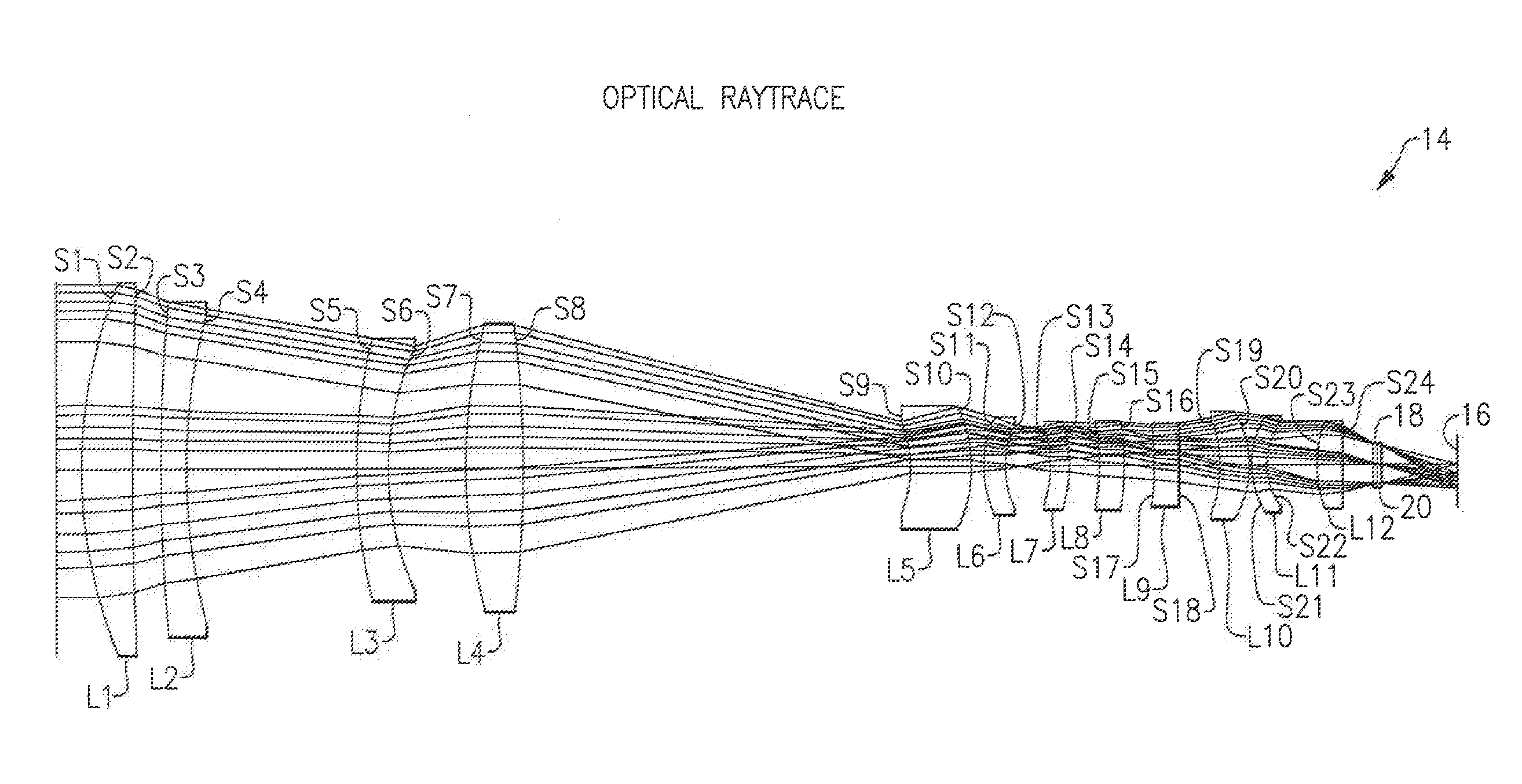
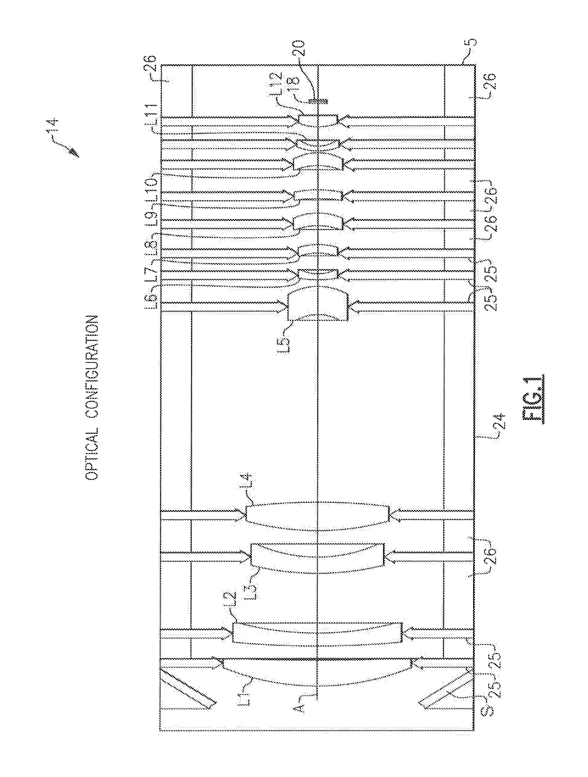
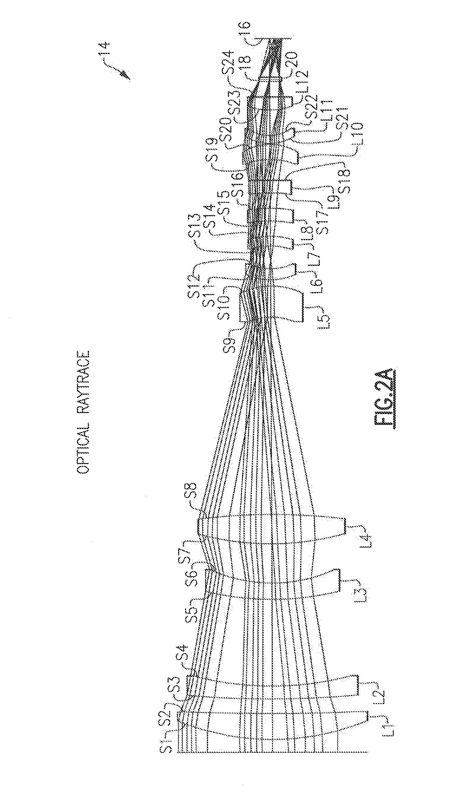
[0041]A preferred embodiment of the lens optical system 14, is diagrammatically shown in FIG. 1. The lens optical system 14 has an overall length, i.e., from a leading surface S1 of the first entrance optical component or lens L1 to surface S29 of the focal plane 16 of the lens optical system 14, of 443.050 mm (17.44 inches). However, it is to be appreciated that the overall length of the lens optical system 14 can vary, from application to application, without departing from the spirit and scope of the present invention. Preferably, the overall length of the optical lens system 14 will typically range between 300 mm (11.81 inches) and 700...


PUM


Abstract

An optical lens system for focusing light on a focal plane for detection by a detector device. The optical lens system comprises a series of optical materials including first and last optical materials with a plurality of other optical materials located therebetween. A housing accommodates the series of optical materials, and each of the optical materials is spaced a desired distance from one another. An external entrance pupil supplies infrared light to the series of optical materials of the optical lens system, and the entrance pupil is located in front of the first optical material. A Dewar window and a filter are located between the last optical material and the focal plane. The optical materials are selected and arranged to focus simultaneously both mid-wave infrared light and long-wave infrared light on the focal plane over a wide temperature range.

Description

[0001]This application claims the benefit of U.S. Provisional Application No. 61 / 1944,083 filed Feb. 25, 2014.FIELD OF THE INVENTION[0002]This invention relates to optical lens systems in general, and more particularly, an optical lens system that operates in infrared regions which is able to capture and simultaneously image, on an imaging plane, both mid-wave infrared and long-wave infrared wavelengths over a wide ranges of operating temperatures of the optical lens systems.BACKGROUND OF THE INVENTION[0003]As is conventional in the prior art, optical systems traditionally operate in either mid-wave infrared regions (MWIR) or long-wave infrared regions (LWIR) but not typically both at the same time. One of the primary reasons for not processing both mid-wave infrared and long-wave infrared wavelengths together is that it is extremely difficult to capture and simultaneously focus both mid-wave infrared and long-wave infrared wavelengths, using a single imaging system comprising a ser...

Claims


Application Information

Patent Timeline
Patent Type & Authority Applications(United States)
IPC IPC(8): G02B13/14G01J5/10G01J5/08G02B7/02G01J5/06
CPCG02B13/146G02B7/028G02B7/021G01J2005/106G01J5/0806G01J5/10G01J2005/0077G01J5/061G02B13/14
Inventor STAVER, PHILIP R.
Owner BAE SYST INFORMATION & ELECTRONICS SYST INTERGRATION INC
Why Eureka
Try Eureka