Boot for hooves

a technology for hooves and boots, applied in the field of boots for hooves, can solve the problems of imbalance in the hoove, different types of damage to the hooves and extremities of horses, and the inability of metal-based hooves to follow the expansion and contraction of the hoove, and achieve the effect of easy mounting and dismounting

Inactive Publication Date: 2015-09-03
SHINGS
View PDF12 Cites 3 Cited by
  • Summary
  • Abstract
  • Description
  • Claims
  • Application Information

AI Technical Summary

Benefits of technology

[0017]The present invention aims at obviating the above mentioned disadvantages of previously known boots for hooves, as well as providing a boot for hooves or hoof boot which is easy to mount and dismount, and which in the mounted position allows a natural hoof mechanism.

Problems solved by technology

Horseshoes manufactured from metal lack the possibility of following the expansion and contraction of the hoof.
Such a horseshoe does not allow contact between the sole and the ground upon compression of the hoof, since the shoe, by its thickness, lifts up the central parts of the hoof, which will hang in the air.
A horseshoe that blocks the sole and the frog from reaching the ground may cause different types of damage to, and deformations in, the hoof and extremity of the horse.
Conventional shoeing also means that the hoof by such trimming is adapted manually to the shoe, since a shoe of metal cannot be sufficiently adapted to the hoof.
This often entails an unnatural hoof shape, which causes imbalance in the hoof and disturbances of the function of the hoof.
An unshod horse may, however, be sensitive to varying grounds when working.
The solution is less suitable because it contains hard parts which may cause the hoof to get caught in surrounding vegetation and possibly to get hurt.
The force from the wire is continuously applied during the time when the hoof boot is mounted, and accordingly also at rest, which may cause discomfort.
The force acting around the hoof also counteracts the hoof mechanism, which ultimately may cause the grip around the hoof in course of time to grow weak so that the hoof boot loosens, or alternatively entails that a pressure harmful in course of time is applied to the hoof.

Method used


Image

  • Boot for hooves
  • Boot for hooves
  • Boot for hooves

Examples


Embodiment Construction

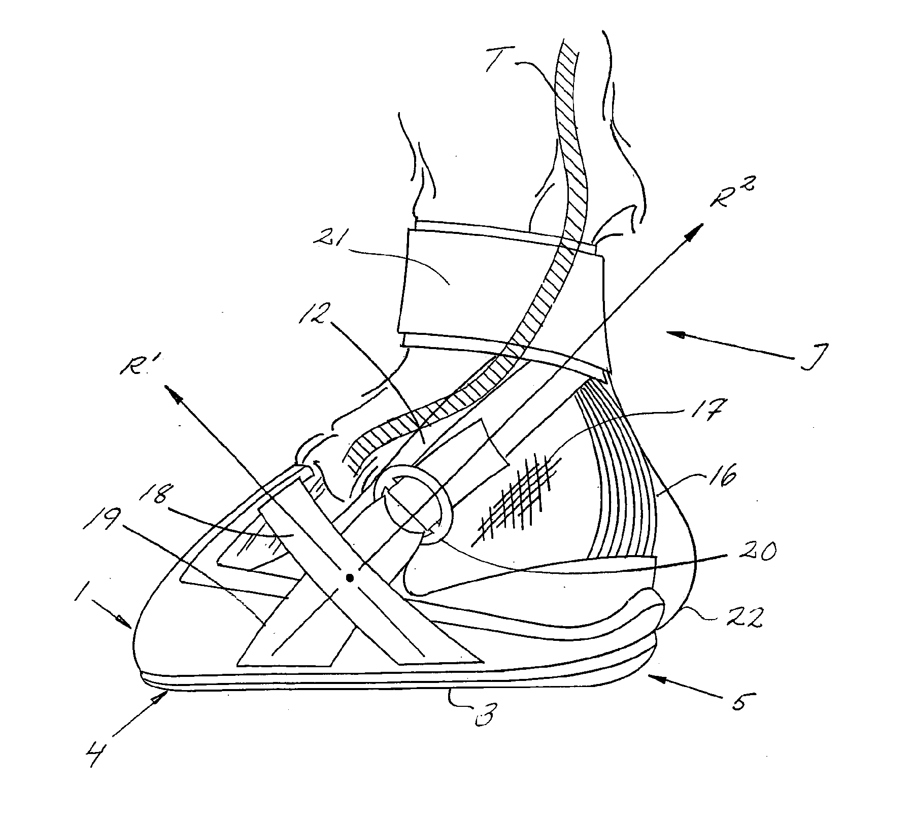
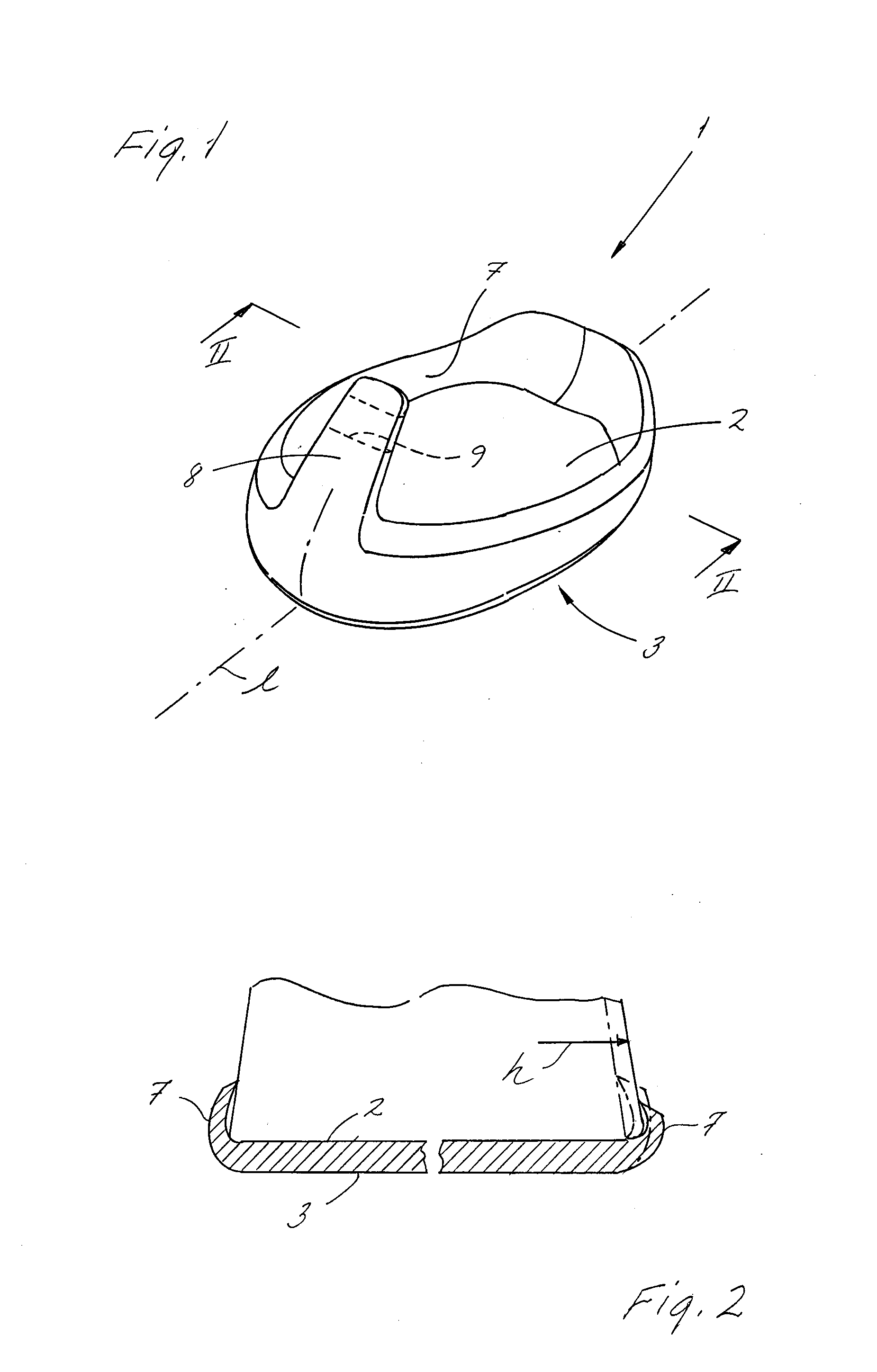
[0060]FIG. 1 shows a sole 1 included in a hoof boot according to the invention. The sole 1 is cup-shaped and comprises a bottom 2 the shape of which essentially corresponds to the underside of a hoof, and the underside of which forms a ground contact surface 3. The ground contact surface 3 is best seen in FIG. 6. The bottom and ground contact surface of the sole extend in the longitudinal direction 1 of the hoof boot between a front toe portion 4 and a rear heel portion 5, see FIG. 5. A protruding edge 7 runs around the bottom of the sole, and has a tongue 8 in the toe portion having such a length that the tongue extends a good distance up along the capsule of the hoof in the mounted position of the hoof boot, as is best shown in FIGS. 7 and 8. A slot 9 mouths in the sides of the tongue 8 and extends through the tongue in ways illustrated by dashed lines in FIG. 1. The slot 9 is adapted for leading through a strap arranged and operative in the way described below. Said strap may alt...


PUM


Abstract

A boot for hooves includes a sole having an external ground contact surface the shape of the underside of a hoof, extending in the longitudinal direction between toe and heel portions. A first strap is anchored in the sole and runs from one side of the hoof boot to the other, across the front side of the hoof in the mounted position. A second strap is anchored in the sole and runs from one side of the hoof boot to the other, above the back side of the hoof in the mounted position, so the first and second straps extend in directions intersecting each other on each side of the hoof boot. The second strap extends from the sole in such a direction that it is adapted to run on the back side of the leg above the hoof.

Description

TECHNICAL FIELD OF THE INVENTION[0001]The present invention relates to a boot for hooves of the type that is attachable to a hoof by means of two straps adjustable in their length.BACKGROUND AND PRIOR ART[0002]Shoes for horses have since antiquity been used to protect the hooves of the horse against wear or to reinforce the hooves. The earliest known horseshoes were of sandal type and manufactured from leather or bast. These shoes are attached to the hoof of the horse by means of straps and cords. It was not until during the 4th century that fittings of iron begun to be nailed into the hoof. The horseshoe most used today is made of a ferrous alloy and attached to the hoof by means of horseshoe nails, wherein the horseshoe is nailed on to the hoof.[0003]Each hoof is, however, unique and individual in its design. The hoof is also variable in the respect that it adapts its shape to the load rate and environment as well as depending on the general health status of the horse.[0004]By hoo...

Claims


Application Information

Patent Timeline
Patent Type & Authority Applications(United States)
IPC IPC(8): A01L3/00A01K13/00
CPCA01K13/007A01L3/00A61F5/0111A01L5/00A61D9/00A61F2005/0197
Inventor NYLUND, MARINA
Owner SHINGS
Why Eureka
Try Eureka