Apparatus for servicing a detector of a fire safety system

a technology for fire safety systems and apparatuses, applied in the direction of instruments, process and machine control, vehicle position/course/altitude control, etc., can solve the problems of time-consuming and expensive for test technicians to reach these detectors to test the functionality, building scaffolding is expensive and time-intensive to build, and bucket lifts are also expensive to use. to facilitate the testing of the detector

Active Publication Date: 2015-09-03
SIEMENS IND INC
View PDF3 Cites 102 Cited by
  • Summary
  • Abstract
  • Description
  • Claims
  • Application Information

AI Technical Summary

Benefits of technology

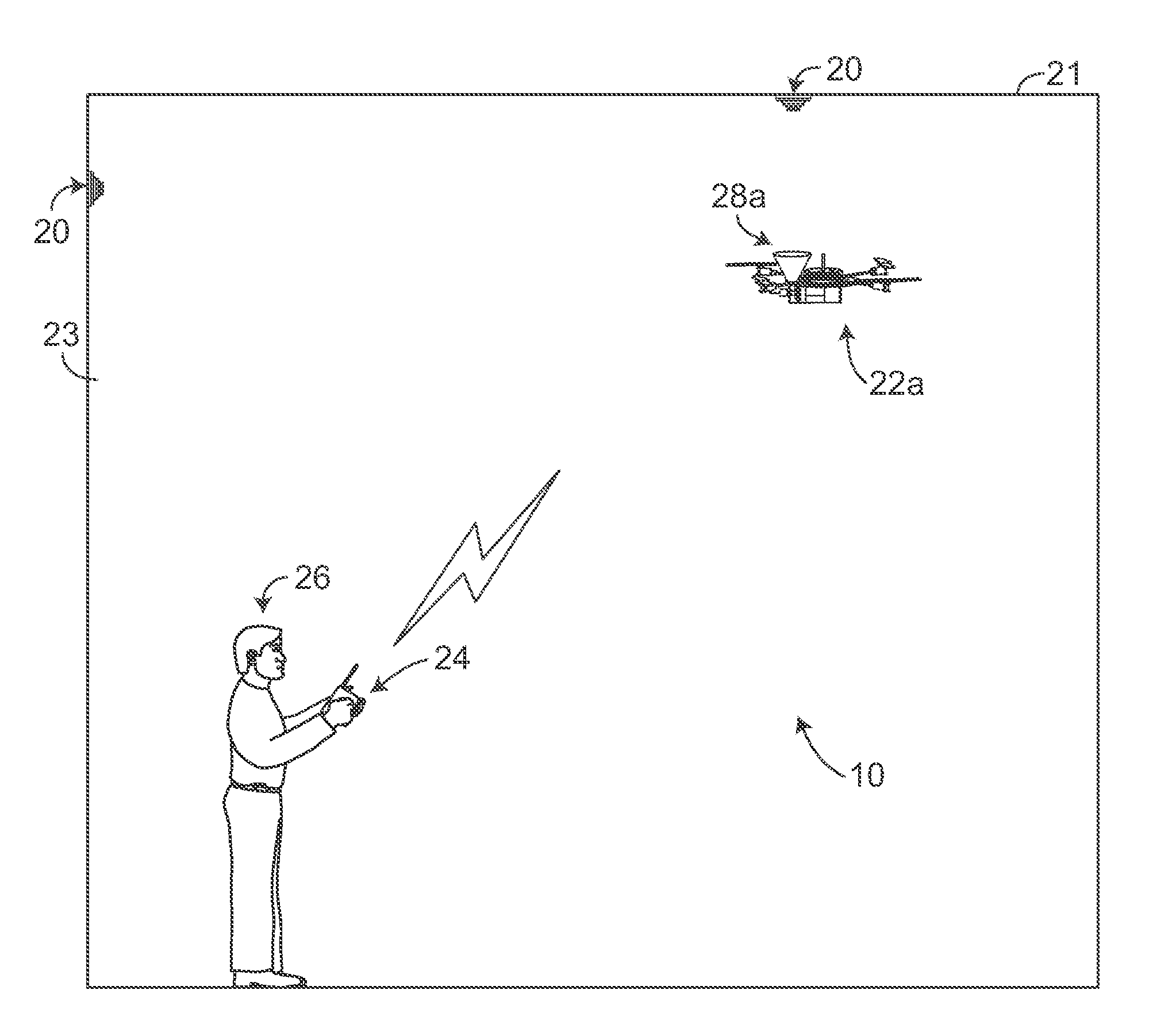
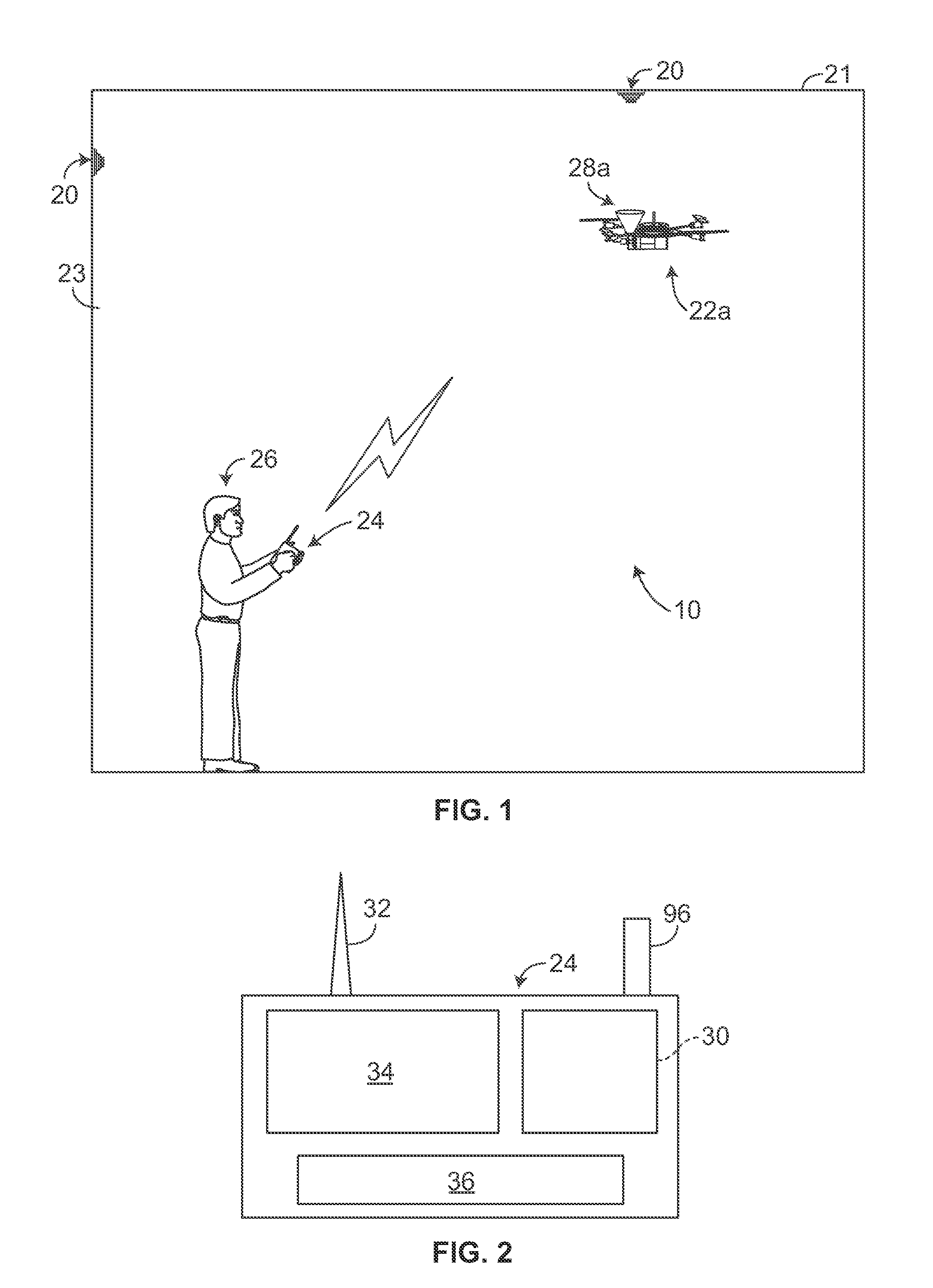
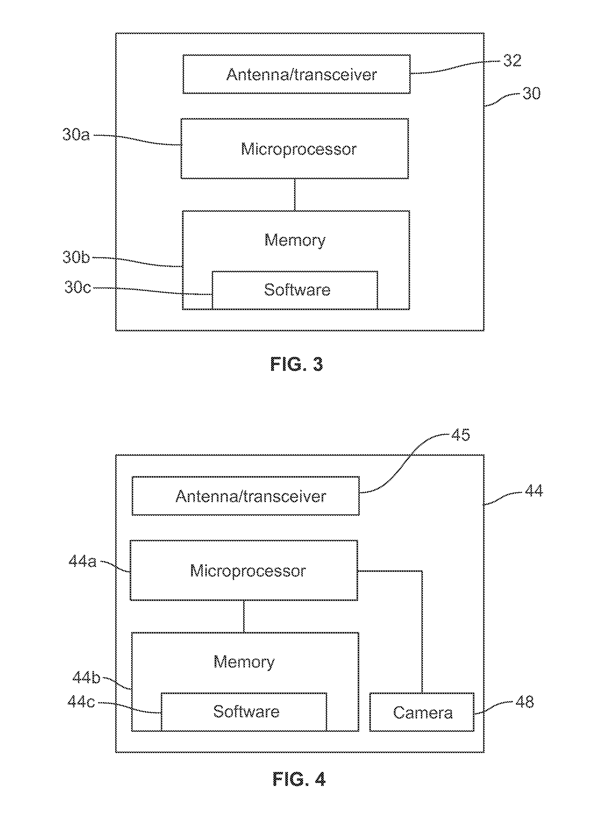
[0004]An apparatus includes an aerial platform which is remotely controlled by an operator using a controller. The apparatus is used to service a detector of a fire safety system. The apparatus includes a frame having a gas canister and a gas delivery cup, preferable formed as a cone, attached thereto, where the gas canister is in fluid communication with the gas delivery cup. The appara...

Problems solved by technology

As a result, it is difficult, time-consuming and expensive for test technicians to reach these detectors to test the functionality.
Currently, test technicians build scaffolding or ride bucket lifts to access the detector, or test technicians gain entry to difficult or dangerous access point...

Method used


Image

  • Apparatus for servicing a detector of a fire safety system
  • Apparatus for servicing a detector of a fire safety system
  • Apparatus for servicing a detector of a fire safety system

Examples


first embodiment

[0027]In the first embodiment shown in FIGS. 6 and 7, the frame 50a has a planar horizontal base wall 58 having an upper surface 58a and a lower surface 58b. The base wall 58 has a larger width or diameter than the chassis 38, such that the chassis 38 is seated on and covers a portion of the upper surface 58a of the wall 58. The gas delivery cup 52 is seated on the upper surface 58a of the wall 58 on another portion thereof that is not covered by the chassis 38 and is mounted between the struts 42, such that the gas delivery cup 52 extends upwardly from the wall 58 so that the open end 56a is above each of the blades 40 and turbulence from the rotating blades 40 is inhibiting from affecting the delivery of gas through the gas delivery cup 52 out of the open end 56a. The gas delivery cup 52 may be vertically mounted on the frame 50a such that the central axis 53 of the gas delivery cup 52 is perpendicular to the plane of the upper surface 58a of the wall 58 of the frame 50a. The open...

second embodiment

[0028]In the second embodiment shown in FIGS. 8 and 9, the frame 50b includes a planar horizontal base wall 60 which has a pair of arms 62, 64 extending therefrom. The base wall 60 has an upper surface 60a and a lower surface 60b. Each arm 62, 64 has a first horizontal wall 66, having an upper surface 66a and a lower surface 66b, which extends outwardly from and in the same plane as the base wall 60, a vertical wall 68, having an inner surface 68a and an outer surface 68b, which extends upwardly from an end of the first horizontal wall 66 of the respective arm 62, 64, and a second horizontal wall 70, having an upper surface 70a and a lower surface 70b, which extends from an upper end of the vertical wall 68 of the arm 62, 64. The chassis 38 is seated on the upper surface 60a of the base wall 60 and the struts 42 extend outwardly from the chassis 38 such that the arms 62, 64 each extend between adjacent struts 42. With this frame 50b, the gas delivery cup 52 may be mounted on the out...


PUM


Abstract

An apparatus includes an aerial platform which is remotely controlled by an operator using a controller. The apparatus is used to service a detector of a fire safety system. The apparatus includes a frame having a gas canister and a gas delivery cup attached thereto, and a drone attached to the frame which is capable of flying the frame under remote control by the operator. A gripping mechanism for gripping a portion of a detector is provided for servicing the detector.

Description

FIELD OF THE INVENTION[0001]The present invention relates to an apparatus for inspecting, testing and servicing a detector, such as smoke or carbon monoxide detector, in a fire safety system.BACKGROUND OF THE INVENTION[0002]Fire safety systems, such as smoke / fire detectors, are often mounted on high ceilings or are mounted in inaccessible places. As a result, it is difficult, time-consuming and expensive for test technicians to reach these detectors to test the functionality. Currently, test technicians build scaffolding or ride bucket lifts to access the detector, or test technicians gain entry to difficult or dangerous access points to access the detector. Building scaffolding is expensive and time intensive to build. Bucket lifts are also expensive to use, and require two operators which increases the cost of this methodology. When multiple detectors must be inspected in one location, these prior art methods are inefficient.[0003]A mechanism for inspecting and testing fire safety...

Claims


Application Information

Patent Timeline
IPC IPC(8): B64C39/02G01D18/00B64B1/06B23P6/00B64D47/08B64B1/40
CPCB64C39/024B64D47/08B64B1/40B64C2201/022B64C2201/12B64C2201/024B64B1/06Y10T29/49721G08B29/145B64U10/30B64U2101/30B64U2201/20B64U10/14B64U20/87B64U2101/26B64U10/13B64U2101/00
Inventor MASTICOLA, STEPHEN P.ZAVROS, STAVROSFIELD, LESLIE A.
Owner SIEMENS IND INC
Why Eureka
Try Eureka