Multi-purpose scanner

Active Publication Date: 2015-09-10
AVISION
View PDF3 Cites 5 Cited by
  • Summary
  • Abstract
  • Description
  • Claims
  • Application Information

AI Technical Summary

Benefits of technology

[0007]Accordingly, the present invention has been proposed to solve the problems of the prior art, and it is an object of the present invention to provide a multi-purpose scanner capable of performing a simplex scan or even a duplex scan on a bo

Problems solved by technology

In addition, it is unnecessary to flatten the angled docume

Method used


Image

  • Multi-purpose scanner
  • Multi-purpose scanner
  • Multi-purpose scanner

Examples


Embodiment Construction

[0021]The present invention will be apparent from the following detailed description, which proceeds with reference to the accompanying drawings.

[0022]The multi-purpose scanner according to each embodiment of the present invention may be a flatbed scanner, a sheet-fed scanner or a combination of the flatbed scanner and the sheet-fed scanner. In addition, the multi-purpose scanner may be a simplex scanner or a duplex scanner. Furthermore, the multi-purpose scanner may be a visible light scanner, an ultra-violet light scanner, an infrared scanner or a combination thereof. Thus, various elements described in the following can be applied to the embodiments when no conflict occurs.

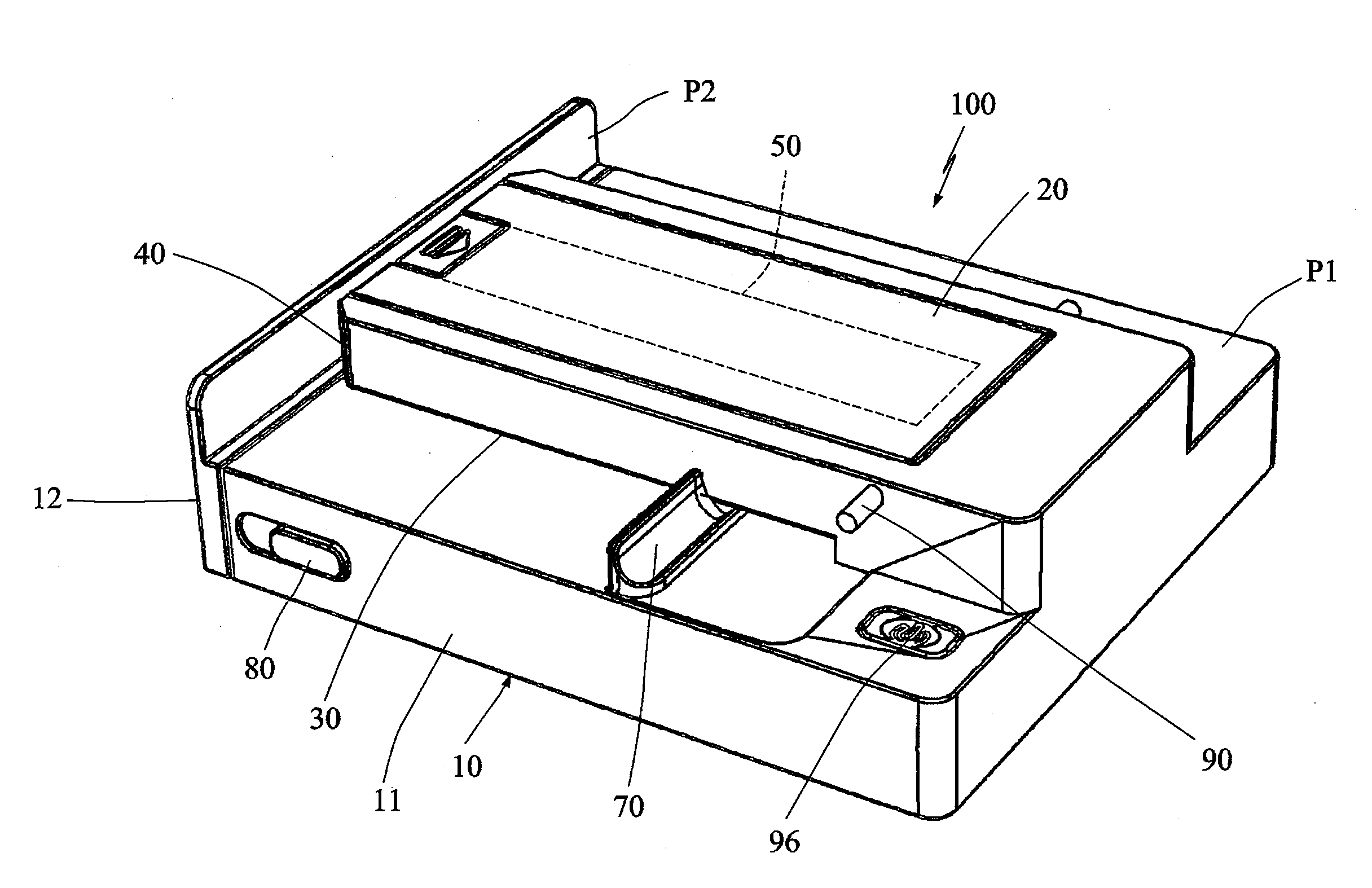
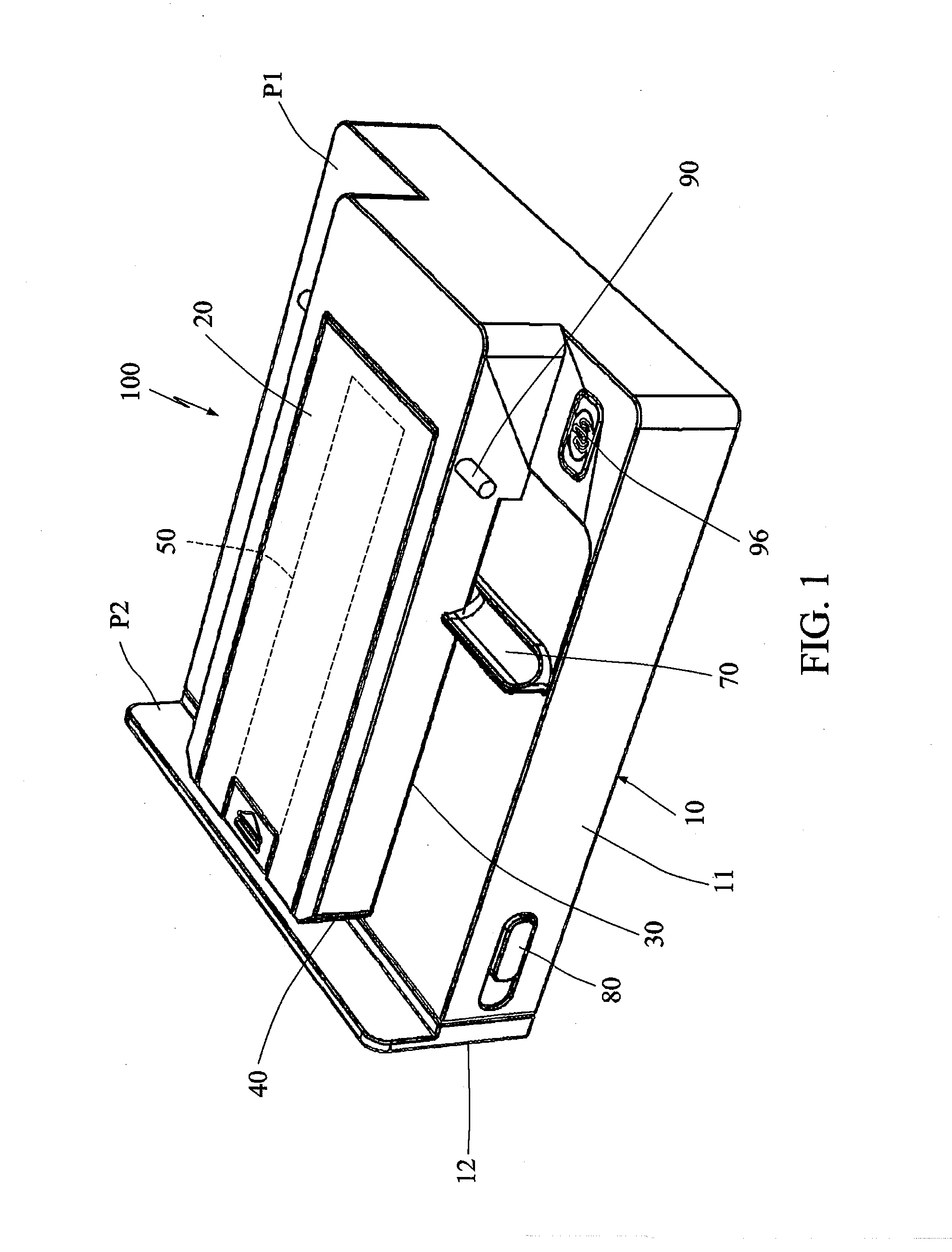
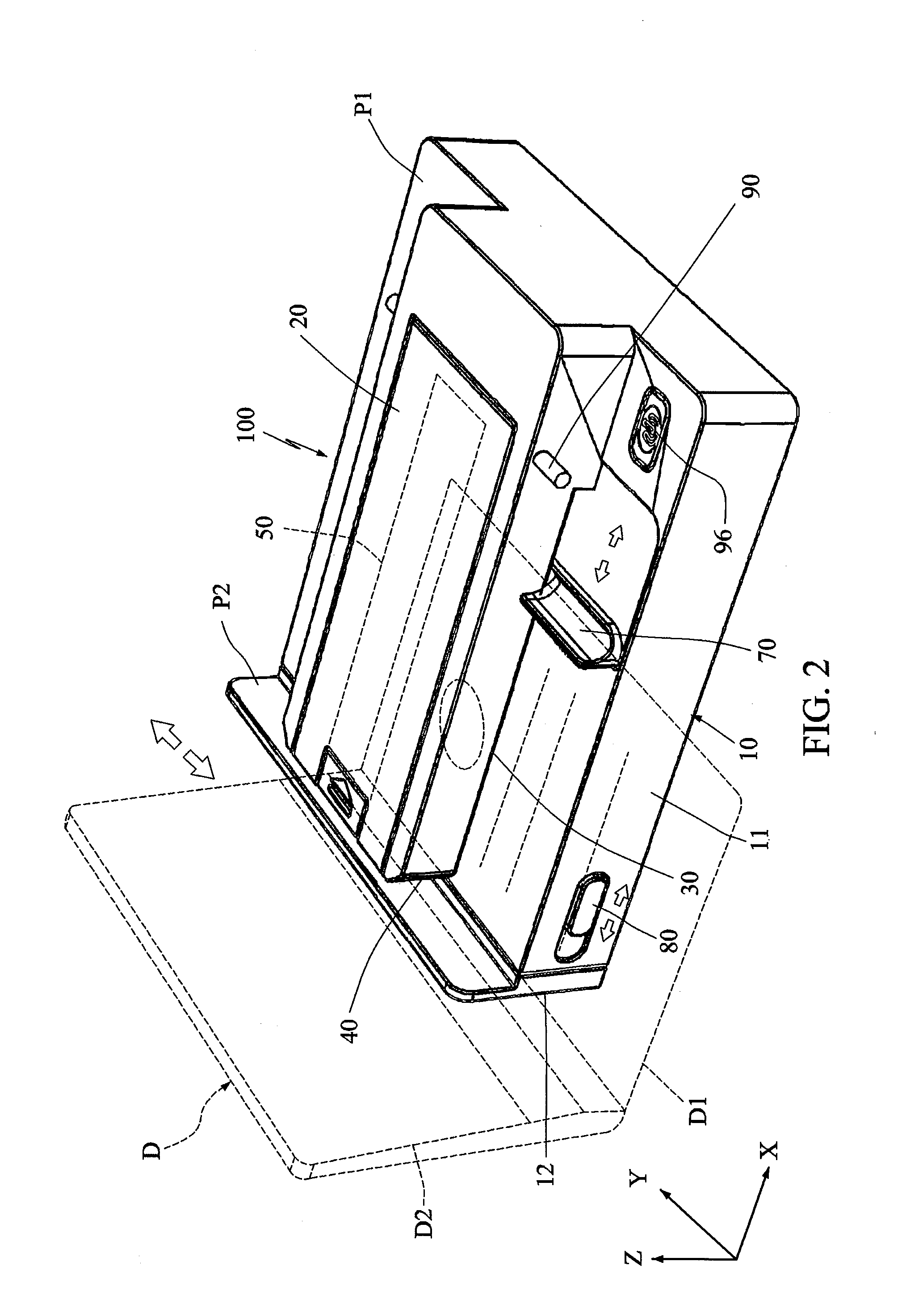
[0023]FIG. 1 shows a pictorial view of a multi-purpose scanner 100 according to a first embodiment of the present invention. FIGS. 2 and 3 show pictorial views of a using state and a maintaining state of the multi-purpose scanner 100 according to the first embodiment of the present invention, wherein FIG. 2 sho...


PUM


Abstract

A multi-purpose scanner comprises a first body, a second body and a scanning module. The second body is disposed on the first body. A first passageway and a second passageway, which are for accommodating a first portion and a second portion of an angled document, and are disposed on a first plane and a second plane, respectively, are formed between the first body and the second body. An included angle is formed between the first plane and the second plane. The scanning module, disposed in the first body and/or the second body, performs an image scan operation on the first portion of the angled document in the first passageway to obtain an image signal.

Description

[0001]This application claims priority of No. 103108068 filed in Taiwan R.O.C. on Mar. 10, 2014 under 35 USC 119, the entire content of which is hereby incorporated by reference.BACKGROUND OF THE INVENTION[0002]1. Field of the Invention[0003]The present invention relates in general to a scanner, and more particularly to a simplex or duplex multi-purpose scanner capable of scanning an ordinary document and a bound document (or even any other angled document).[0004]2. Related Art[0005]In general, when a bound document, such as a passport, book or the like, is to be scanned, the bound document cannot be transported past a sheet-fed scanner because the left and right sides of the bound document have different thicknesses, or due to the book back or binding mode. So, a flatbed scanner must be utilized to acquire the document image. However, the drawback of the flatbed scanner is that the flatbed scanner cannot scan both sides of the bound document at the same time. So, the user has to tu...

Claims


Application Information

Patent Timeline
IPC IPC(8): H04N1/203H04N1/00H04N1/028
CPCH04N1/2038H04N2201/0434H04N1/00525H04N1/02815H04N1/00716H04N1/00827H04N1/121H04N1/123H04N1/2032H04N1/2036
Inventor CHEN, CHI-YAOLIU, JUI CHENGPENG, CHAO YU
Owner AVISION
Why Eureka
Try Eureka