Illuminating device

a technology of illumination device and light source, which is applied in the direction of lighting and heating apparatus, semiconductor devices for light sources, and light support devices, etc., can solve the problems of affecting consumers' willingness to pay higher prices, and the illuminating device is not an ideal member of interior design, so as to achieve better illumination and flexible adjustment of different shapes of the illuminating devi

Inactive Publication Date: 2015-09-17
LOOMA LIGHTING COMPANY
View PDF5 Cites 16 Cited by
  • Summary
  • Abstract
  • Description
  • Claims
  • Application Information

AI Technical Summary

Benefits of technology

[0006]The present invention is directed to an illuminating device. By using a belt structure such like tape measure, different shapes of the illuminating device can be feasibly adjusted. As a result, it solves the problem of limited viewing angle and provides better illumination.

Problems solved by technology

However, limited viewing angle of LED is a major problem which affects consumers' willingness to pay higher price for LED bulbs, LED lamps or other LED lighting devices.
Furthermore, because of the limited viewing angle, LED illuminating device is not an ideal member for interior design owing to its passable lighting effects.

Method used


Image

  • Illuminating device
  • Illuminating device
  • Illuminating device

Examples


Embodiment Construction

[0020]The detailed explanation of the present invention is described as follows. The described preferred embodiments are presented for purposes of illustrations and description, and they are not intended to limit the scope of the present invention.

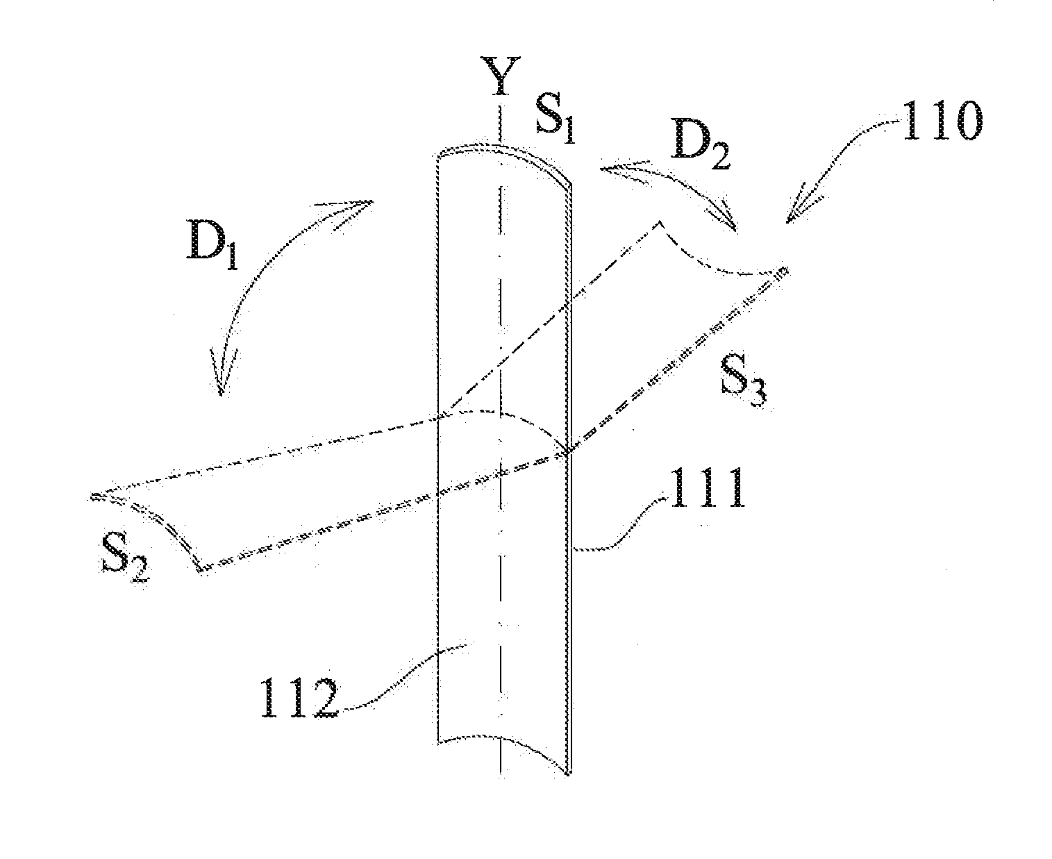
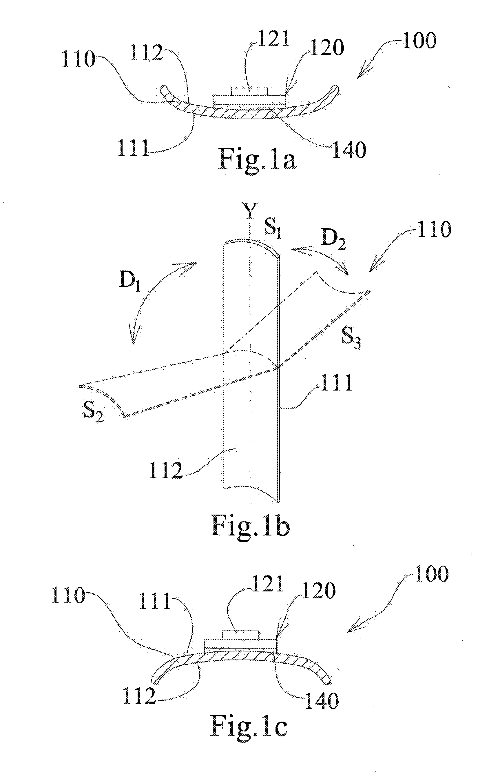
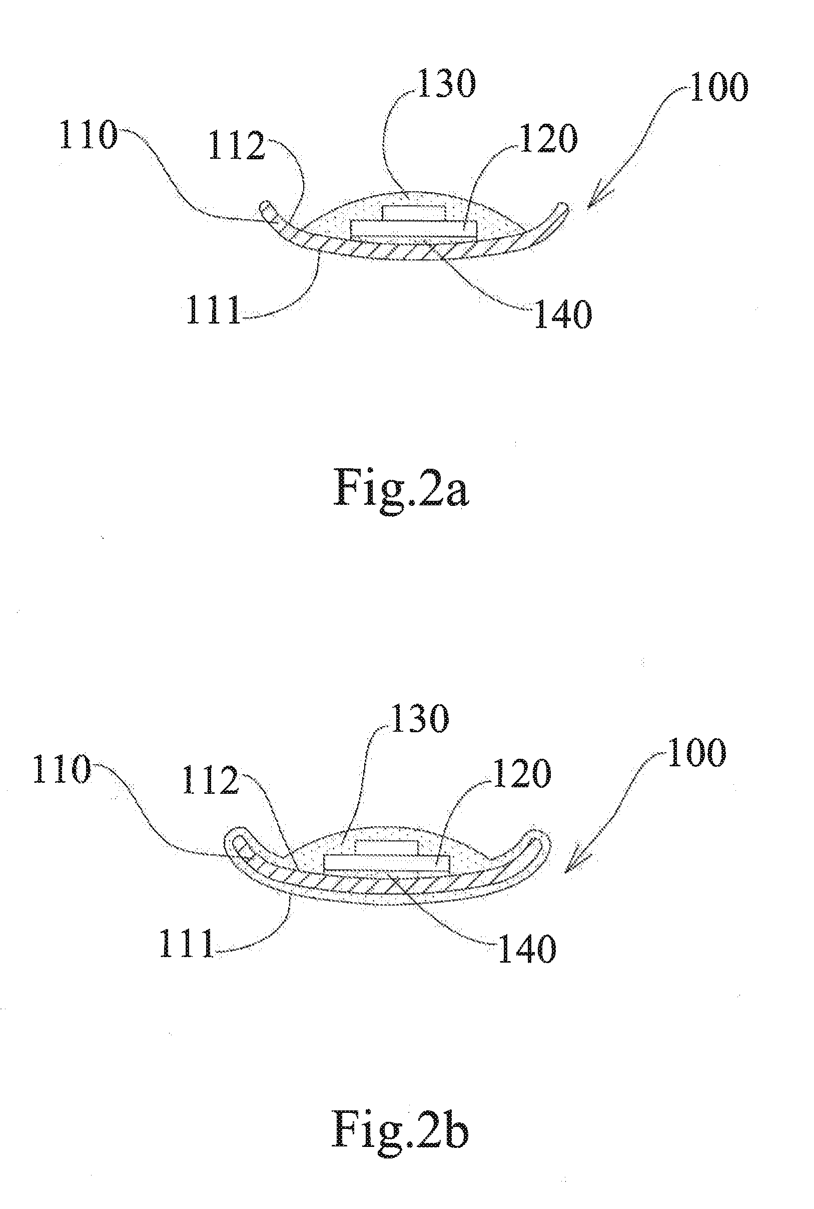
[0021]Referring to FIGS. 1a, 1b and 1c, an illuminating device 100 comprises a bendable carrier 110 and at least a bendable light emitting diode stripe 120, The bendable carrier 110 has a belt structure with an arcuate cross-section (as illustrated in FIG. 1a and FIG. 1c), and includes a convex surface 111 and a concave surface 112, to firmly maintain the bendable carrier 110 in an elongated state S1 when the bendable carrier 110 is not bent (as shown in FIG. 1b); it also enables the bendable carrier 110 to recover to the elongated state from a bent state S2, S3. In one embodiment, the bendable carrier 110 can be a stainless steel tapeline or a manganese steel tapeline. The bendable light emitting diode stripe 120 comprises multiple light ...


PUM


Abstract

The present invention is directed to an illuminating device. The illuminating device comprises a bendable carrier and at least a bendable light emitting diode stripe. The bendable carrier has a belt structure with an arcuate cross-section, and includes a convex surface and a concave surface, to firmly maintain the bendable carrier in an elongated state when the bendable carrier is not bent; it also enables the bendable carrier to recover o the elongated state from a bent state. The bendable light emitting diode stripe comprise multiple light emitting diode chips, wherein the bendable light emitting diode stripe is directly arranged on the convex surface or the concave surface or interior space of a flexible tube. By using a belt structure such like tape measure, different shapes of the illuminating device can be feasibly adjusted. As a result, it solves the problem of limited viewing angle and provides better illumination.

Description

BACKGROUND OF THE INVENTION[0001]1. Field of the Invention[0002]The present invention relates to an illuminating device, and more particularly to a bendable illuminating device.[0003]2. Description of the Prior Art[0004]Light emitting diodes (LED) have gradually become the mainstream of the illuminating device for its energy-saving, short reaction time and long lifespan. However, limited viewing angle of LED is a major problem which affects consumers' willingness to pay higher price for LED bulbs, LED lamps or other LED lighting devices. Furthermore, because of the limited viewing angle, LED illuminating device is not an ideal member for interior design owing to its passable lighting effects.[0005]In this consideration, an illuminating device which is bendable and can be easily adjusted to desired shape should be developed to solve the problem of limited viewing angle.SUMMARY OF THE INVENTION[0006]The present invention is directed to an illuminating device. By using a belt structure...

Claims


Application Information

Patent Timeline
Patent Type & Authority Applications(United States)
IPC IPC(8): F21S4/00F21V31/00F21K99/00
CPCF21S4/006F21K9/30F21Y2103/003F21Y2101/02F21V31/005F21V7/0016F21V7/005F21S4/22F21K9/20F21Y2105/10F21Y2103/10F21Y2115/10
Inventor CHO, KUO-HSIUNG
Owner LOOMA LIGHTING COMPANY
Why Eureka
Try Eureka