Connecting element

a technology of connecting elements and connecting elements, applied in the direction of couplings, mechanical control devices, controlling members, etc., can solve the problems of unsuitability of the construction of the known connecting elements for mechanical loads acting in the assembly direction, sled deformation under the influence of mechanical loading, and construction complexity. achieve the effect of latching

Inactive Publication Date: 2008-07-08
FICO CABLES
View PDF23 Cites 18 Cited by
  • Summary
  • Abstract
  • Description
  • Claims
  • Application Information

AI Technical Summary

Benefits of technology

[0019]The sled according to the invention comprises a sufficient large opening in assembly position so that fastening ends having a different shape and size can be received therein. First the displacement of the sled from said assembly position to said fastening position leads to a specifically minimizing of this opening and in this manner to an enclosing of a defined volume. In this volume, spherical, pyramidal, cubic and other conceivable structures of fastening ends can be received and, thus, effectively latched. Said latching is supported by an adaptation of the inner shape of the sled to the shape of the fastening end to be received. Accordingly, a spherically shaped fastening end and a suitably shaped sled serve for providing a connection having many degrees of freedom. A fastening end having other shapes or structures serves for example for the provision of an axial connection with no degree of freedom.

Problems solved by technology

Linked and releasable connecting of two components by means of an appropriate connecting element is a problem in many fields of mechanical engineering.
This is only possible if the connecting element consists of components with limited constructive complexity.
The mechanical deformability additionally however causes that the sled deforms under the influence of mechanical loading.
Additionally, the construction of the known connecting elements is unsuitable for mechanical loads acting in assembling direction because their elastical deformability of the sled material would lead to a fast wear of the bearing area and therefore to a disengagement of the spherical head.
However, these supporting areas are too small to withstand permanent tensile or tensile / compressive cyclic loading.

Method used


Image

  • Connecting element
  • Connecting element
  • Connecting element

Examples


Embodiment Construction

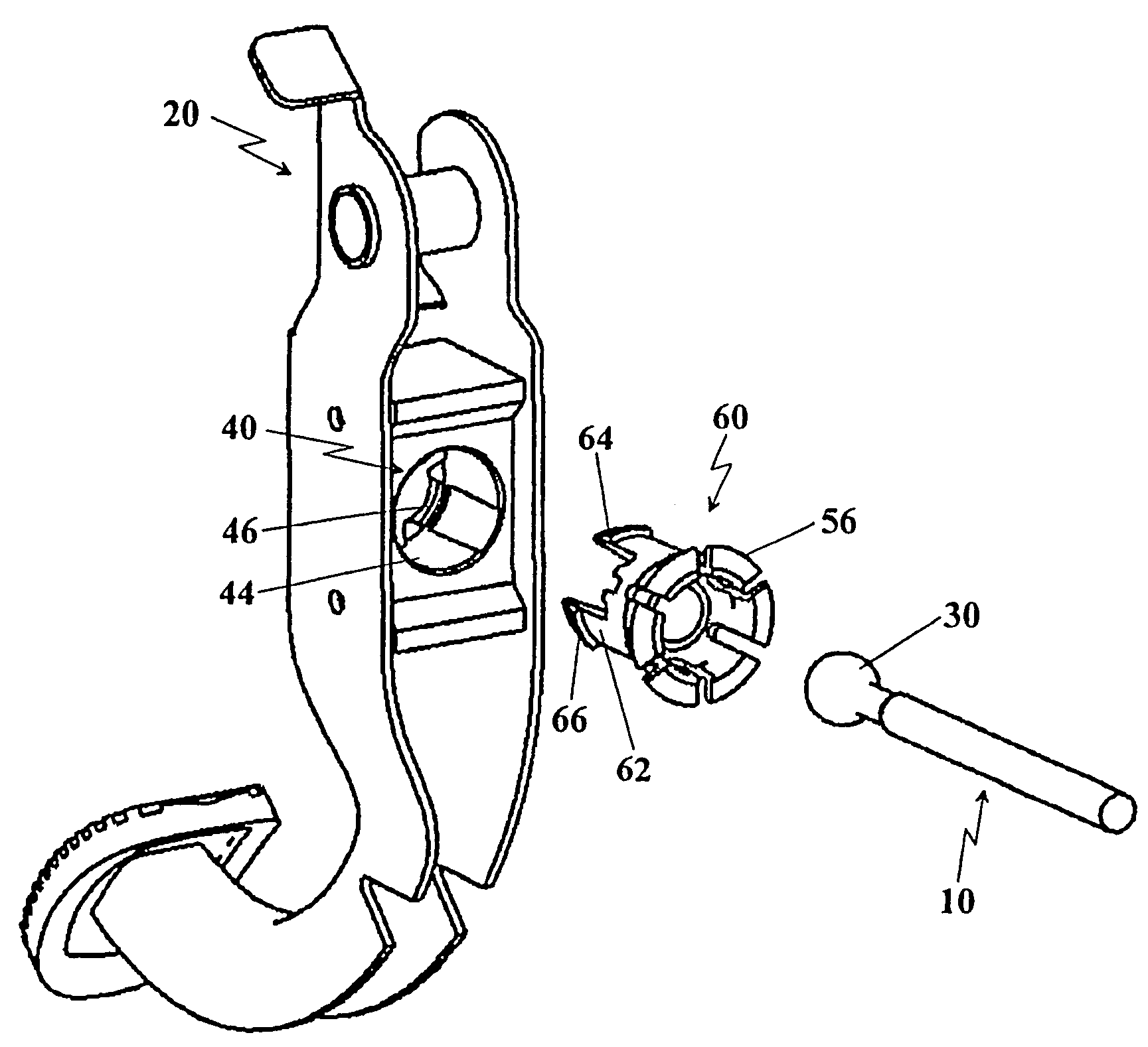
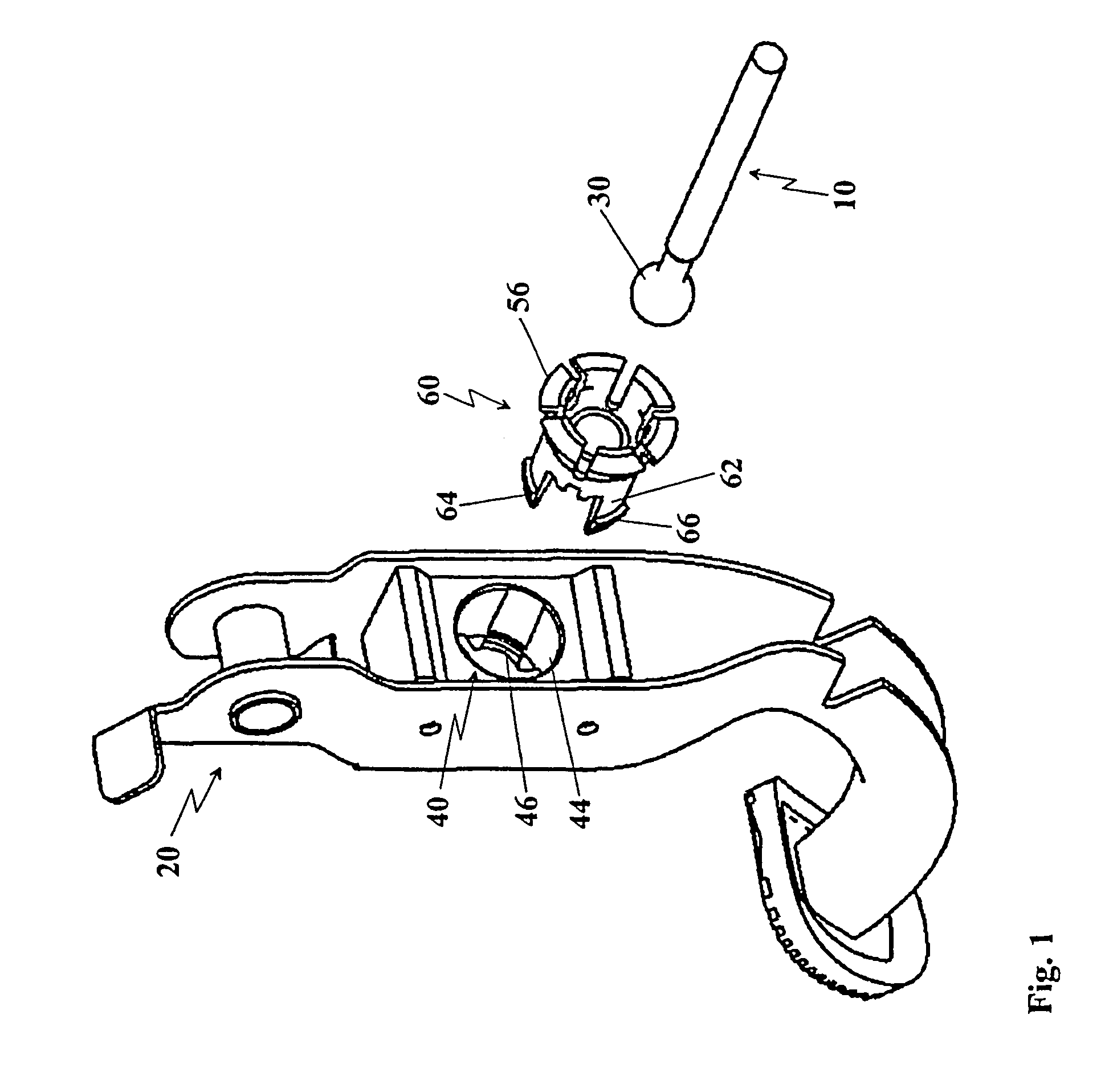
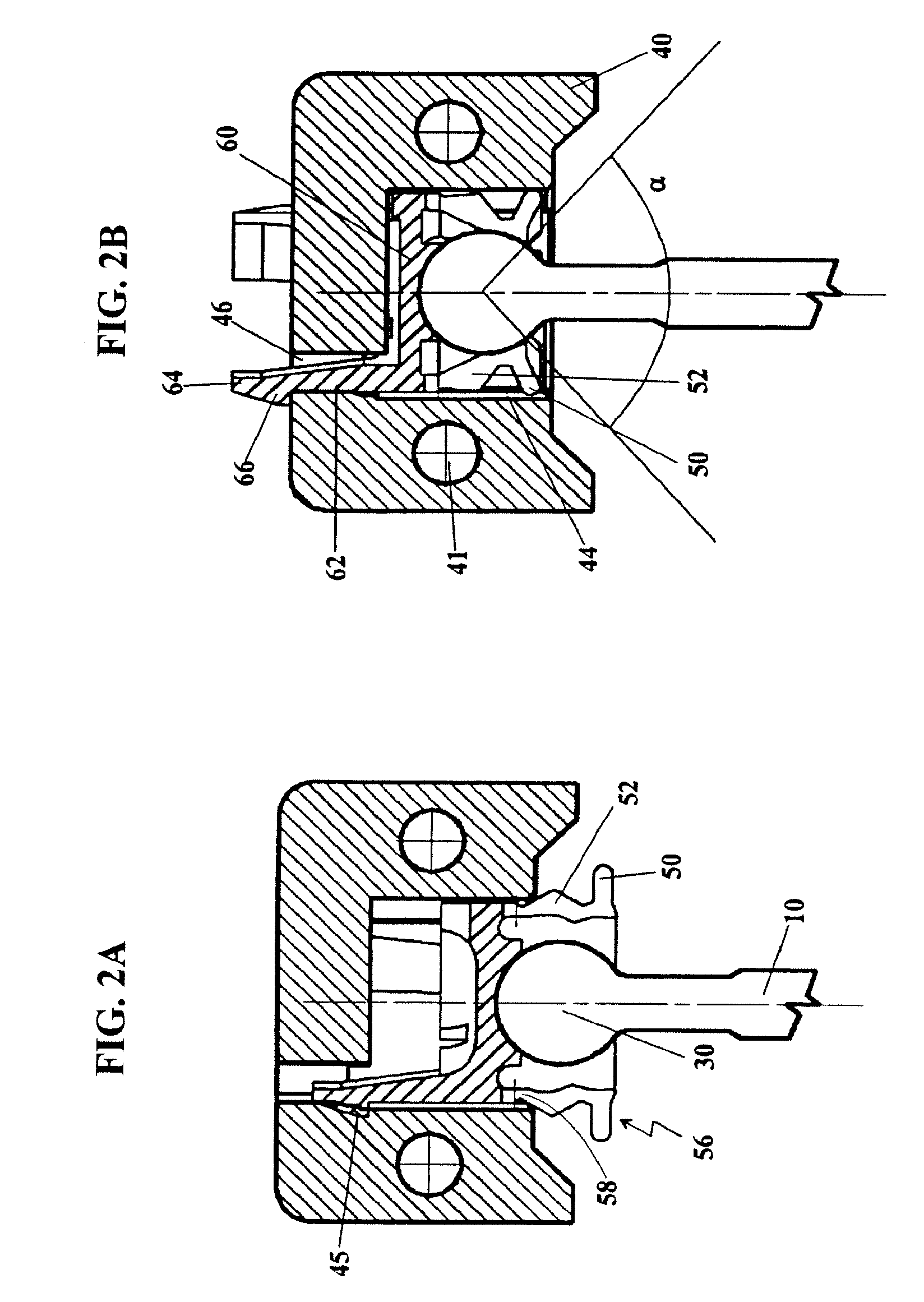
[0039]Referring to FIG. 1, the connecting element 40, 60 according to the invention for connecting a first part 10 (preferably a brake or a clutch linkage) with a second part 20 (preferably a pedal) comprises connecting means 40 and a sled 60 arranged in said connecting means 40. Said sled 60 serves for receiving a fastening end 30 of said first part 10 to be subsequently latched in said connecting means 40.

[0040]Said connecting means 40 is preferably according to the invention made of one piece and is formed by a housing 40 which is connected to said second part 20 or which is integrated therein. It is possible according to the first embodiment of the present invention to configure said connecting means 40 in such a way that it can latchably receive said sled 60.

[0041]Preferably according to the invention, said sled 60 comprises a hollow cylindrical shape having two opposed ends. The one end of said sled 60 serves for receiving and mounting said fastening end 30. The other end serv...


PUM


Abstract

A connecting element is illustrated, suited for releasably connecting a first component and a second component, particularly for releasably connecting an actuator with a pedal of a motor vehicle, wherein forces parallel to the assembly direction are transmitted by the connecting element. The connecting element comprises a connecting mechanism which is attached to the second component and a sled, which can receive a fastening end of the first part and which latches in the connecting mechanism in its fastening position. The connecting mechanism is preferably configured in one-piece-form as a housing, wherein the sled, which is connected to the actuator, is connected to the housing in fastened condition and wherein the sled can be released by means of a tool.

Description

1. TECHNICAL FIELD[0001]The present invention relates to a connecting element for releasable connecting a first component with a second component, for instance a modulator with an operating element. In particular, the present invention relates to a connecting element for releasable connecting an actuator linkage with a pedal in a vehicle.2. PRIOR ART[0002]Linked and releasable connecting of two components by means of an appropriate connecting element is a problem in many fields of mechanical engineering. The construction of vehicles is such a field. Here, usually the applied force to the brake or clutch pedal and the thereby generated torque is transmitted via a movably attached linkage of bars or modulator to the brake or clutch system, respectively. Such releasable connections have the following advantages: The moving direction of the two connected components can be turned round, the transmitted torques and forces can be changed by exploiting the lever principle and the aspect of ...

Claims


Application Information

Patent Timeline
Patent Type & Authority Patents(United States)
IPC IPC(8): F16C11/00B60T7/06F16C11/06G05G1/00G05G1/30G05G1/46
CPCB60T7/06F16C1/14F16C11/069G05G1/46G05G1/30Y10T403/32631F16C2361/45Y10T403/606B60T11/18F16C9/04F16C11/0657F16C11/0695F16D2025/081
Inventor DONA CONTERO, JUAN M.GRAS, DAVID ALONSO
Owner FICO CABLES
Why Eureka
Try Eureka