Beverage maker having a lockable actuation rod

a technology of actuation rod and beverage maker, which is applied in the direction of beverage vessels, mixers, mixing, etc., can solve the problems of actuation rod slipping out, unsatisfactory hygiene, and complicated operation, and achieve the effect of simple and reliable manner and avoiding incorrect operations

Inactive Publication Date: 2015-08-18
PI-DESIGN AG
View PDF35 Cites 28 Cited by
  • Summary
  • Abstract
  • Description
  • Claims
  • Application Information

AI Technical Summary

Benefits of technology

[0005]It is therefore an object of the present invention to specify a beverage maker having a preparation element on an actuation rod, in which the actuation rod can be locked in a simple and reliable manner for the purpose of removing the beverage, and incorrect operations can be avoided.
[0013]The closure fixes the grip element in its lower position in the retaining position. As a result, the actuation rod is effectively locked. In order to achieve this fixing, the closure is designed such that it is pivotable with respect to the lid between the closed position and the retaining position about a horizontal pivot axis which runs transverse to the longitudinal axis. As a result, it is possible to design the closure such that it can be pivoted into the retaining position only when the grip element is in its lower position since, otherwise, the actuation rod would get in the way. To this end, the closure can preferably be pivoted over the grip element from the closed position to the retaining position when the grip element is in or close to its lower position.
[0014]The closure is preferably designed such that it at least partially covers the grip element at the top in the retaining position and as a result locks it. To this end, the grip element can be designed to be asymmetrical with respect to the longitudinal axis, so that said grip element has a region close to the axis and a region which projects from the region close to the axis transverse to the longitudinal axis and faces away, for example, from the removal opening of the lid in the retaining position. This projecting region then preferably runs at a distance from the lid (in particular from a top wall of the lid) in the lower position of the grip element in order to make it easier for the finger of a user to operate the grip element. The closure then preferably at least partially covers the projecting region of the grip element in the retaining position. However, in other refinements, the closure can also cover, and thereby fix, the grip element in another region, for example in a region which is offset through approximately 90° about the longitudinal axis in relation to the removal opening, or the closure can clamp into the grip element at its radial outer face instead of covering it.
[0017]The pivot axis preferably runs behind the longitudinal axis as seen from the removal opening, that is to say it is at a greater minimum distance from the removal opening than the longitudinal axis. This facilitates design of the closure such that it projects over the lid toward the rear by way of its actuation region in the retaining position, so that it can be easily released from the retaining position again. In addition, this rearward arrangement of the pivot axis leads to the pivot region of the closure being only very small when the actuation rod is withdrawn, so that it is not possible to inadvertently remove the beverage from the vessel when the actuation rod is fully or partially withdrawn.
[0020]The closure preferably has a substantially rigid support and a closure body which is connected to said support and can project, for example, into the removal opening or can rest on the cover so as to surround the removal opening and, in the process, closes the removal opening in a sealing manner. In particular, this closure body can be produced from a softer material than the support and, for example, be injection-molded onto the support in a two-component injection-molding process. The support preferably has two arms which are guided from the closure body past the passage opening (and therefore the actuation rod) on both sides and of which the free ends are connected to the lid in a pivotable manner in the region of the pivot axis. A spring element can also be formed on the support (or on the lid) at a distance from the closure body, said spring element acting on the closure in the direction to the retaining position by way of a spring force in the closed position. This facilitates pivoting of the closure from the closed position to the retaining position after the latching connection between the second latching structure and the lid is released. This spring element can likewise be produced from a softer material than the support, in particular from the same material as the closure body, and can be injection-molded on the support together with said closure body.

Problems solved by technology

However, this operation is somewhat complicated and not completely satisfactory in respect of hygiene.
However, if the grip element is not in its lowermost position, the closure can nevertheless be actuated, without the grip element being locked, and the actuation rod can nevertheless slip out during pouring in the event of incorrect operation of this kind.

Method used


Image

  • Beverage maker having a lockable actuation rod
  • Beverage maker having a lockable actuation rod
  • Beverage maker having a lockable actuation rod

Examples


Embodiment Construction

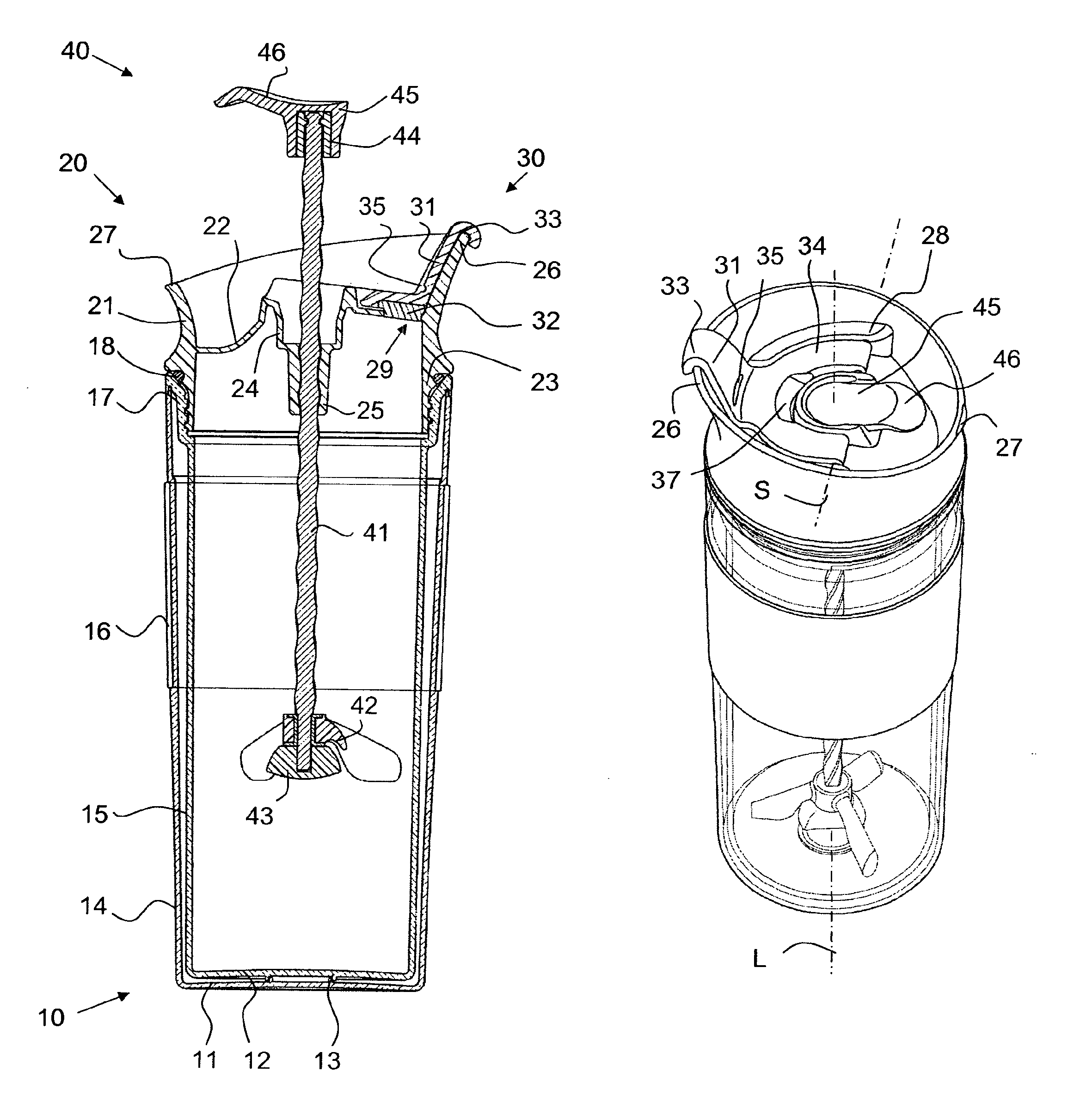
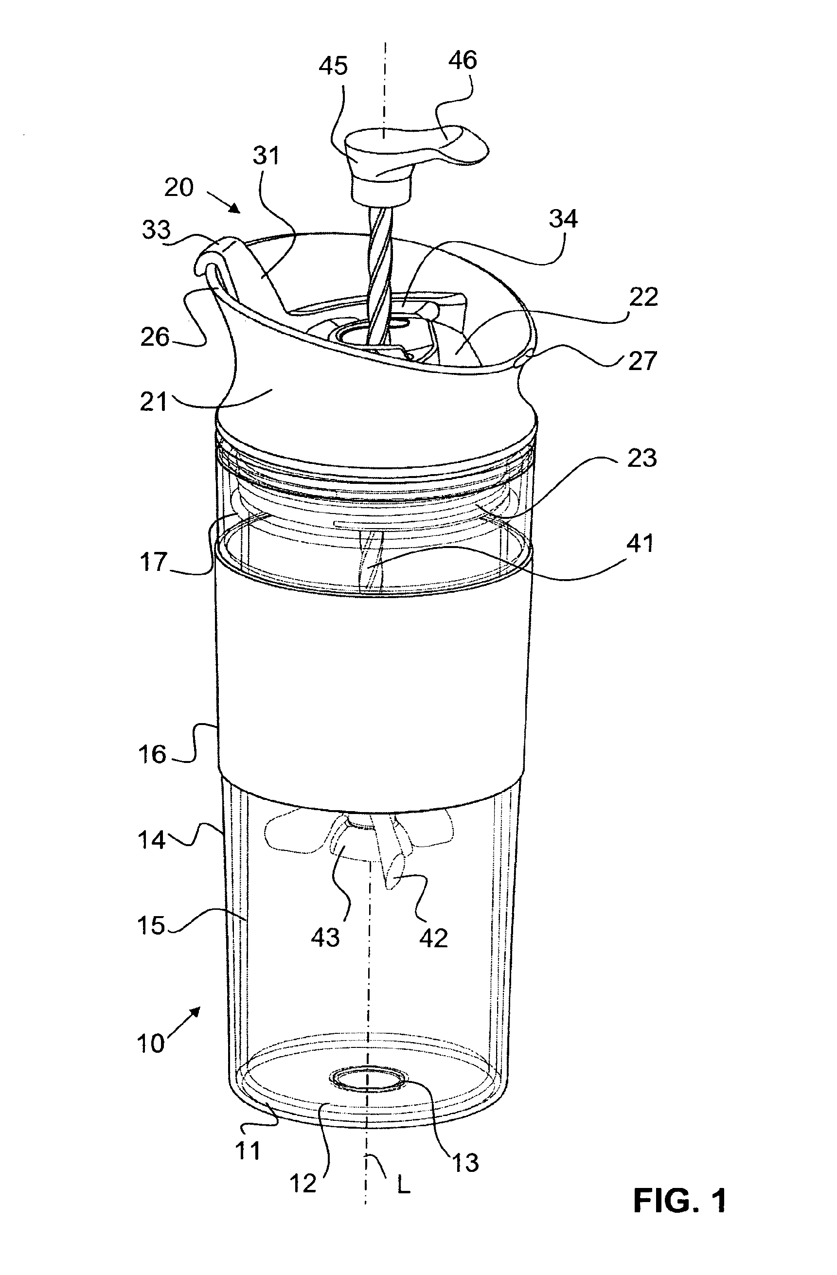
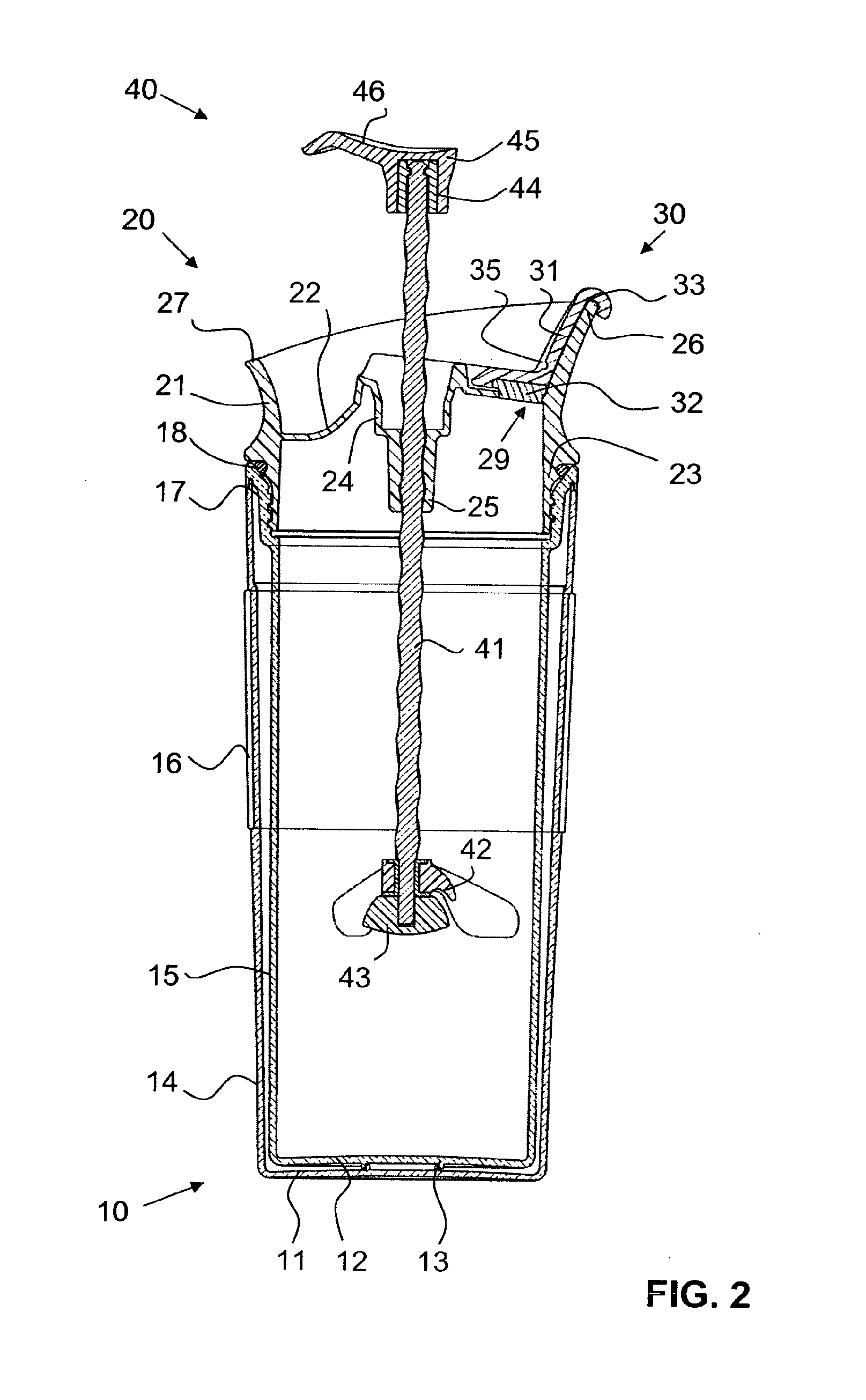
[0031]FIGS. 1 to 4 illustrate a beverage maker according to the invention in line with a first embodiment. The beverage maker comprises a double-walled vessel 10 which is composed of a transparent plastic, having an outer base 11, an inner base 12, an outer side wall 14 and an inner side wall 15. The inner base 12 rests on the outer base 11 in an annular connection region 13. The outer side wall 14 and the inner side wall 15 are connected to one another, in particular welded to one another, in their upper border region. A collar 16 which is composed of a relatively soft material, for example silicone rubber, is situated in a slight recess in the outer side wall 14 on the outer face thereof and surrounds the outer side wall 14 in this region. An internal thread 17 for connecting the vessel 10 to the lid 20 is formed in an upper edge region of the inner side wall 15.

[0032]The lid 20 has a peripheral casing wall 21 which widens toward the top. The casing wall extends further upward in ...


PUM


Abstract

The invention relates to a beverage maker, which comprises a container (10) that is open at the top thereof and a lid (20) that covers the container. A removal opening (29) is formed in the lid. A vertical actuation rod (41) passes through the lid. Inside the container, a preparing element (42), for example, a mixing element, is attached to the actuation rod. Outside the container, a grip element (45) is attached to the actuation rod. The grip element can be moved together with the actuation rod between a lower position and an upper position. A closure (30) can be swiveled about a horizontal swivel axis between a closed position that doses the removal opening and a retaining position that releases the removal opening, wherein in the retaining position, the closure fixes the grip element in the lower position thereof. The actuation rod is thereby effectively prevented from sliding out through the removal opening when the beverage is removed.

Description

CROSS REFERENCE TO RELATED APPLICATIONS[0001]This application is a National Stage of International Application No. PCT / CH2011 / 000189, filed on Aug. 3,2010, which claims priority from Swiss Patent Application No. 00508 / 10, filed on Apr. 8,2010, the contents of all of which are incorporated herein by reference in their entirety.TECHNICAL FIELD[0002]The present invention relates to a beverage maker which has a vessel which is open at the top and a lid which covers the vessel and has a removal opening. An actuation rod having a preparation element attached to it, for example a mixing element, a frothing element or a plunger filter, passes through the lid and can be moved between a lower and an upper position with respect to the lid. A closure closes the removal opening in the lid in a closed position. The actuation rod is locked in its lower position by the closure when said closure assumes a retaining position.PRIOR ART[0003]The prior art discloses plunger-filter coffee makers (often c...

Claims


Application Information

Patent Timeline
Patent Type & Authority Patents(United States)
IPC IPC(8): A47J43/10A47J31/00A47J43/042A47J31/44
CPCA47J43/105A47J31/00A47J31/44A47J43/042
Inventor BODUM, JORGEN
Owner PI-DESIGN AG
Why Eureka
Try Eureka