Remote range finding based target positioning method, device, and unmanned plane
A target positioning and ranging device technology, applied in the field of unmanned aerial vehicles, can solve the problems of difficult to effectively obtain the accurate position of the target, large deviation of the target position, and complicated calculation process, so as to shorten the judgment time, complete efficiently and simplify the processing The effect of the process
- Summary
- Abstract
- Description
- Claims
- Application Information
AI Technical Summary
Problems solved by technology
Method used
Image
Examples
Embodiment 1
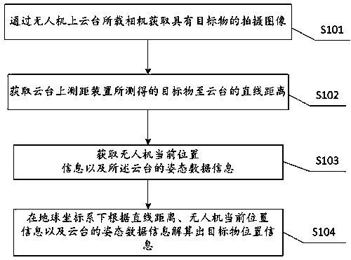
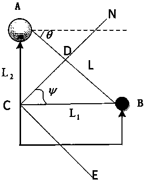
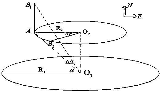
[0035] With the rapid development of drone technology, drones are used in various fields. Usually, the UAV is equipped with a camera on the gimbal to obtain images, and the range finder installed on the UAV is used to measure the distance of the target in front, but there is no method for remote target positioning based on UAV ranging. In order to obtain the position of the target in the captured image, at present, the positioning technology based on the video image of the UAV is usually used to process the video image information collected by the camera in real time, and then compare the pixel position of the target in the video image with the map. By comparison, the position of the target can be found out. The position of the target obtained by this method not only has a large deviation, but also takes a long time to judge, the calculation process is complicated, and it is difficult to effectively obtain the accurate position of the target. In order to solve this problem, th...
Embodiment 2
[0068] Figure 4 It is a structural block diagram of a target positioning device based on remote ranging provided by an embodiment of the present invention. The device includes: a shooting module, a ranging module, a positioning module, a posture perception module, and a calculation and processing module, wherein the shooting module uses for obtaining photographed images with objects;
[0069] The distance measurement module is used to obtain the linear distance L from the distance measurement position to the target object; the positioning module is used to obtain the current position information of the target positioning device; the posture perception module is used to perceive the posture of the distance measurement module or the shooting module Data information, wherein the attitude data information includes pitch angle and heading angle; the calculation processing module is used to solve the problem according to the straight line distance L, the current position informatio...
Embodiment 3
[0072] On the basis of the above-mentioned embodiments, this embodiment provides an unmanned aerial vehicle, which includes a camera, a distance measuring device, an attitude sensor, a positioning device, a flight controller, and a three-axis gimbal; wherein, the The camera is used to obtain the shot image with the target object; the distance measuring device is used to measure the straight-line distance L to the target object; the attitude sensor is used to perceive the attitude data information of the platform; the positioning device is used for Receive the position information of unmanned aerial vehicle in real time; The three-axis cloud platform is used to carry the camera and the distance measuring device, and adjust the camera shooting angle and the distance measuring direction of the distance measuring device; Wherein, the three-axis cloud platform includes a cloud platform control The pan-tilt controller is used to receive images captured by the camera, ranging data fro...
PUM
 Abstract
Description
Claims
Application Information
 - R&D
- Intellectual Property
- Life Sciences
- Materials
- Tech Scout
- Unparalleled Data Quality
- Higher Quality Content
- 60% Fewer Hallucinations
Browse by: Latest US Patents, China's latest patents, Technical Efficacy Thesaurus, Application Domain, Technology Topic, Popular Technical Reports.
© 2025 PatSnap. All rights reserved.Legal|Privacy policy|Modern Slavery Act Transparency Statement|Sitemap|About US| Contact US: help@patsnap.com


