Cord holder with integral locking mechanism

a technology of locking mechanism and locking coil, which is applied in the direction of machine supports, curtain suspension devices, other domestic objects, etc., can solve the problems of not doing anything to avoid tangles and becoming problematic for heavier items, and achieve the effect of effective locking the coil and facilitating loading and unloading of the coil

Inactive Publication Date: 2007-03-13
JERRY A DAVIS FAMILY TRUST
View PDF7 Cites 29 Cited by
  • Summary
  • Abstract
  • Description
  • Claims
  • Application Information

AI Technical Summary

Benefits of technology

[0013]When in use, the collar surrounds and contains a coiled cord in order to hold the coil together. A cord holder made with a closed collar may be slipped down over the coil and then tilted so that the shank engages the upper portion of the coil. The coil will then be locked into place by pulling it down firmly against the backside of the shoulder of the shank. When using an open collar device, the coil may be draped over the back of the shank and then tucked between the open ends of the arms of the collar and pulled snug. Each of these and other related methods effectively locks the coil from unraveling; the shank providing support while also locking the coil into place. Various functional shapes of the shank facilitate loading and unloading of the coil within the collar and provide various means of suspension. The design of the cord holder is such that it allows any length of cord to be in use with the remaining coils held tightly in place.

Problems solved by technology

We can surmise that because the process of rope making was quite tedious, once it had been made, the rope would have been stored for reuse.
This method works well for thin flat cords or tapes, but becomes problematic for heavier items.
Though a simple peg works well for storage on a wall, it does nothing to avoid tangles when the coil is removed from the peg.

Method used


Image

  • Cord holder with integral locking mechanism
  • Cord holder with integral locking mechanism
  • Cord holder with integral locking mechanism

Examples


Embodiment Construction

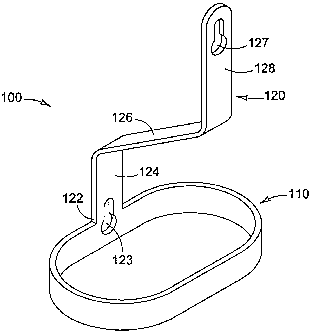
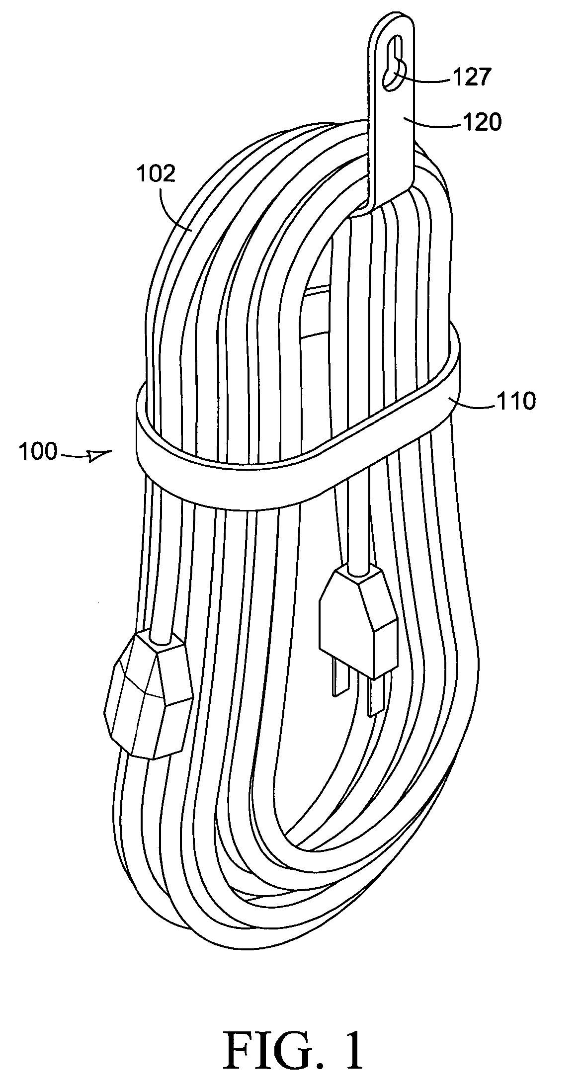
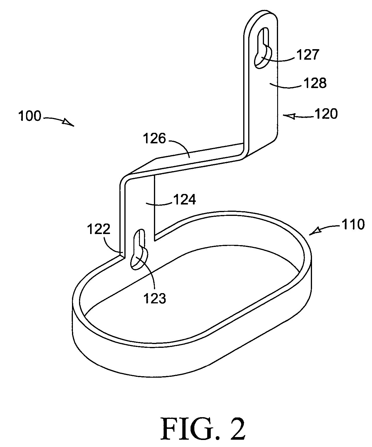
[0034]The preferred embodiment of a cord holder 100 in the present invention is shown in use in FIG. 1, where it supports and contains a coil 102 of electrical extension cord for storage. As depicted in FIG. 2, an empty cord holder 100 exhibits the basic theme, being shown in the same orientation in which it will normally be used. It comprises two basic portions, namely, a collar 110 with an integral shank 120 rising orthogonally from the collar 110. The proximal end of the shank 120 emerges from the collar 110 into the base 122 of the neck 124. The neck 124 rises into a shoulder 126, which extends to the upper shank 128 at the distal end of the shank 120. The angle between the collar 110 and the shoulder 126, after discounting the offset due to the length of the neck 124, will generally be about 45°, and seldom greater than 60°, depending upon the size, weight and flexibility of the coil 102 to be supported by the cord holder 100. The collar 110 may be closed as in FIG. 2, or open,...


PUM


Abstract

This cord holder may be used for storage or transport of any coiled elongate article, such as a rope or electrical cord. It comprises a collar that surrounds and contains the coil, and a shank that extends away from the collar and forms a shoulder across the collar. The shank supports the coil to keep it from falling through the collar or otherwise becoming tangled or uncoiled. The collar may be open or closed, and the shank may take on various angles and shapes to accommodate a variety of coiled elongate articles. This cord holder may be made from a variety of materials and is scalable in size to accommodate varying loads. Methods of use are shown that include mounting brackets and transport features.

Description

CROSS-REFERENCES TO RELATED APPLICATIONS[0001]Not ApplicableStatement Regarding Federally Sponsored Research or Development [0002]Not ApplicableSequence Listing or Program [0003]Not ApplicableDESCRIPTIONField of the Invention[0004]The present invention relates to an apparatus for holding an elongate article for display, or for packaging, or for arranging such an article in an organized manner to facilitate sale, transport, or storage. Although the held article often will be removed from the apparatus when the article is in use, there are many applications wherein the apparatus will be used as a retainer to organize the extra unused length of held articles. The described apparatus may be used with cord-like articles in the broadest sense, including electrical cords and wire, ropes, cables, hoses, tubing, straps, and the like.BACKGROUND[0005]In the class of elongate objects, rope is probably the oldest. Though the beginning of rope making has been lost in prehistory, there is evidence...

Claims


Application Information

Patent Timeline
Patent Type & Authority Patents(United States)
IPC IPC(8): A47F5/00B65H75/36B65H75/44
CPCB65H75/366
Inventor DAVIS, JERRY A.
Owner JERRY A DAVIS FAMILY TRUST
Why Eureka
Try Eureka